3g interfaces diagram
Home » Wallpapers » 3g interfaces diagramYour 3g interfaces diagram images are ready in this website. 3g interfaces diagram are a topic that is being searched for and liked by netizens today. You can Find and Download the 3g interfaces diagram files here. Get all free photos and vectors.
If you’re looking for 3g interfaces diagram pictures information linked to the 3g interfaces diagram topic, you have pay a visit to the ideal site. Our site frequently provides you with hints for refferencing the highest quality video and picture content, please kindly search and find more enlightening video content and images that fit your interests.
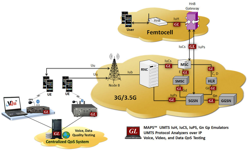
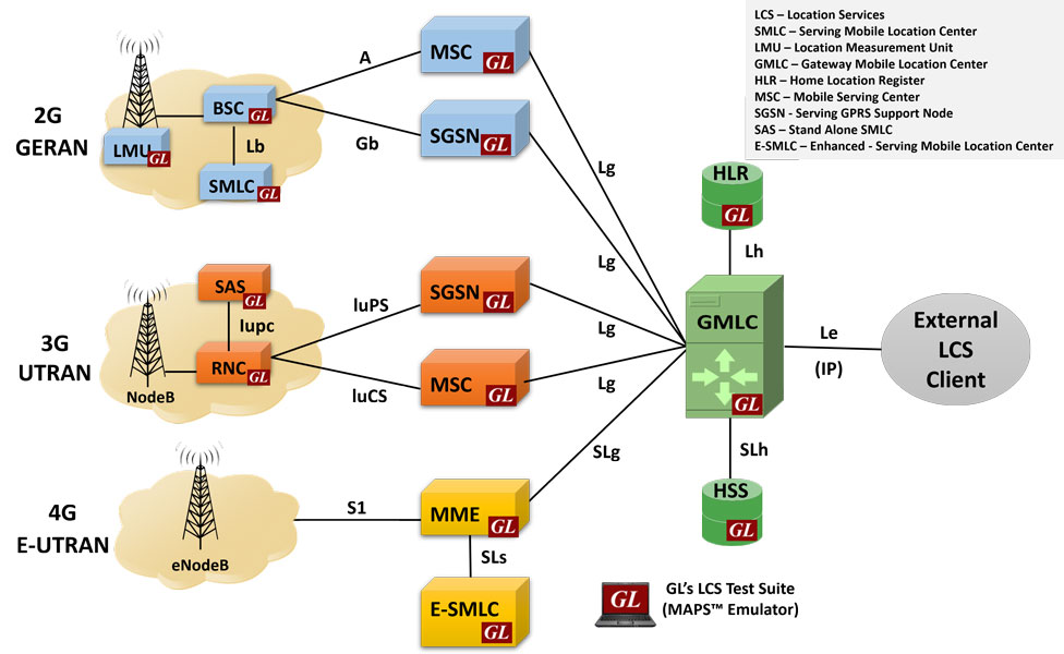
3g Interfaces Diagram. The control plane is used to ensure availability of the transmission plane. 3G-UMTS Call Flow Originating Call User UE-RNC Sessions UTRAN RNC-Core Network Sessions Core EventStudio System Designer Equipment Network UE RRC RNC SCCP Iu MSCVLR 06-Oct-13 0724 Page 3 UE applies the ciphering keys and also starts integrity protection in the return direction RRC Security Mode Complete rrc rrc Security Mode Complete ranap ranap DTAP MM CM Service Accept The Core. GSM Circuit Switched Call Flows. Bit rate up to 2 Mbps.
 3g Networks Analysis And Simulation From gl.com
The control plane is used to ensure availability of the transmission plane. The MS of GSM is referred as user equipment UE in UMTS. Conceptual network model. All elements within 3G UMTS wireless infrastructure can be tested with GLs general-purpose protocol simulation tool - MAPS which supports simulation of various interfaces of 3G UMTS IuCS IuPS IuH IuPC GPRS Gb Gn Gp interfaces using MAPS UMTS. Interfaces are allowing MME SGW and PGW cooperating with other network elements eg. Interact with routing entities.
GSM Handover Call Flows.
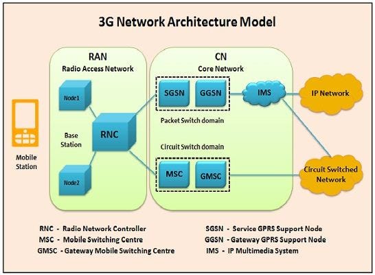
The UMTS network architecture is partly based on existing 2G network components and some new 3G network components. Explaining the Interfaces in LTE. Transmission plane provides means for exchange of the user data. The interfaces between the different parts of the system are denoted Uu S1 and SGi as shown below. 3 GSM top diagram is making the. The FDD version of UTRA is so well known that discussions about any of the other 3G radio interfaces are usually framed as comparisons with it.
 Source: forum.huawei.com
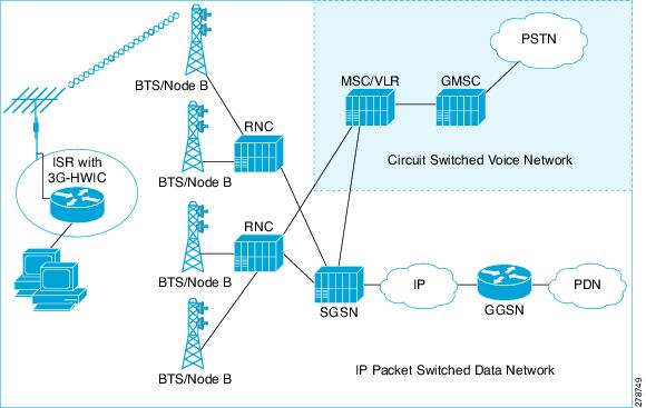
Figure Work on 4G standardisation started in interfaces Adaptive Multi-Rate to ITU-T 4 illustrates a tower with two mobile 2004 just as 3G started to take-off. Overview of 3G Mobile Networks and the MobileNext Broadband Gateway Third generation 3G mobile networks define three components of the overall path from mobile station to IP network. It inherits the basic functional elements from the GSM architecture on the core network CN side. Interact with routing entities. The part of the network that is accessed via the SGSN is often referred to as.
 Source: cablefree.net
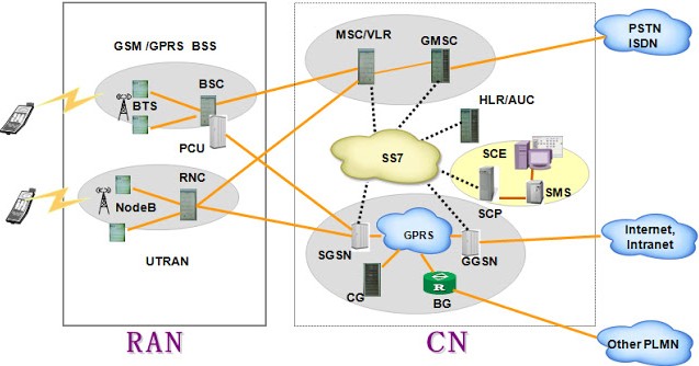
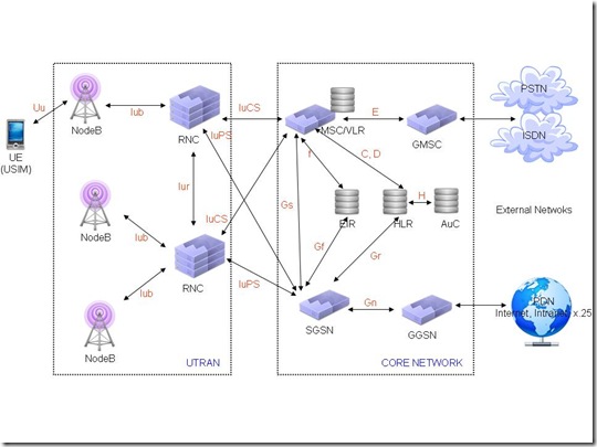
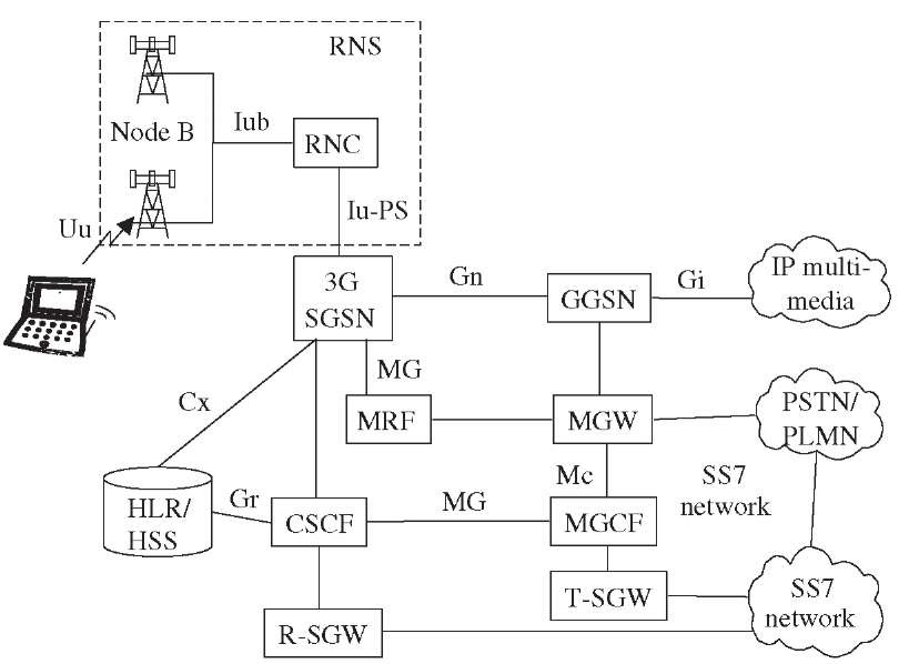
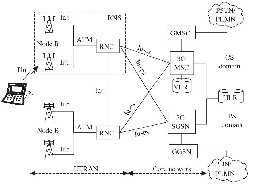
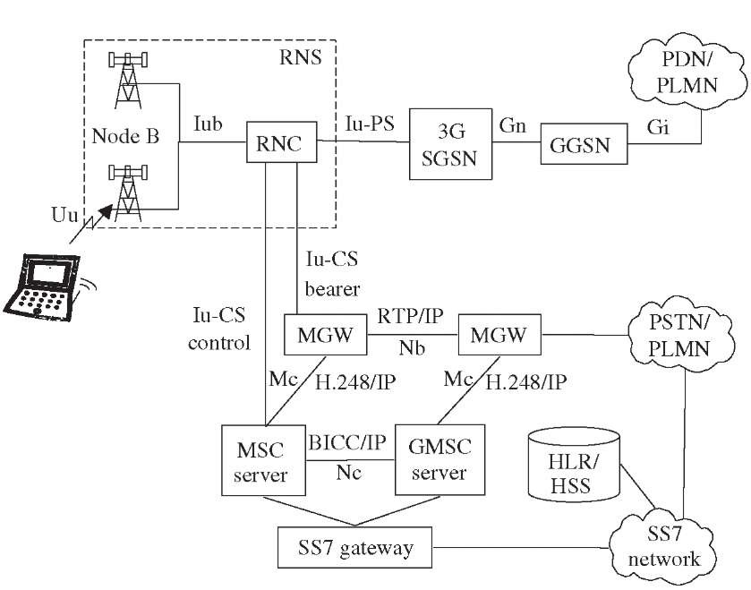
Below graph shows the interface names between different nodes in addition to the protocols that the nodes are using to communicate between each other. It includes UmGbGnGpGiGrGcGfGd and Gs interfaces. Browsing at the time of voice communication. After familiarising with main network elements time has come to better know interfaces between those elements. It inherits the basic functional elements from the GSM architecture on the core network CN side.
 Source: medium.com
The User Equipment UE The internal architecture of the user equipment for LTE is identical to the one used by UMTS and GSM which is actually a Mobile Equipment ME. The MSC has quite similar functions both in GSM and UMTS. 3 GSM top diagram is making the. The UMTS network architecture is partly based on existing 2G network components and some new 3G network components. Bit rate up to 2 Mbps.
 Source: sebbank256.blogspot.com
3G SGSN Serving GPRS Support Node Similar to that of MSC VLR but is used for Packet Switched PS services. The link between every two nodes is having a unique interfaces name. The overall radio access network ie. Both the UE and the UTRAN are composed of different layers. Browsing at the time of voice communication.
 Source: 3glteinfo.com
Below diagram shows the interfaces exist between the MS and the GGSN in user plan in 3G network The RNS means Radio Network Subsystem. Browsing at the time of voice communication. Figure Work on 4G standardisation started in interfaces Adaptive Multi-Rate to ITU-T 4 illustrates a tower with two mobile 2004 just as 3G started to take-off. The User Equipment UE and the UMTS Terrestrial Radio Access Network UTRAN. And it contains the RNC and the NodB.
 Source: cisco.com
The MS of GSM is referred as user equipment UE in UMTS. Interfaces and their protocol stacks. The radio network subsystem is also known as the UMTS Radio Access Network or UTRAN. Delay requirements for delay sensitive real time traffic. The network architecture can be divided into subsystems based on the nature of traffic protocol structures physical elements.
 Source: what-when-how.com
Interfaces are allowing MME SGW and PGW cooperating with other network elements eg. The radio frequencies used the air interface options used between the mobile device and base station and the entire network architecture including interfaces between components. International Mobile Subscriber Identity IMSI is a unique identifier allocated to each mobile subscriber Its code type is E212 IMSI can be saved in SIM HLR and VLR and can be transferred through MAP and Wireless interface. The MSC has quite similar functions both in GSM and UMTS. Delay requirements for delay sensitive real time traffic.
 Source: researchgate.net
The radio frequencies used the air interface options used between the mobile device and base station and the entire network architecture including interfaces between components. GSM GPRS Sequence Diagrams. Bit rate up to 2 Mbps. ISDN User Part ISUP Call Flows. User Equipment The 3G system consists of two main parts.
 Source: gl.com
SIP and H323 Call Flow Diagrams. 3G UMTS Sequence Diagrams. Collectively all the Radio Network Subsystem is known as the UTRAN UMTS Radio Access Network. The overall radio access network ie. Description of 3G architecture.
 Source: ques10.com
The MSC has quite similar functions both in GSM and UMTS. User Equipment The 3G system consists of two main parts. International Mobile Subscriber Identity IMSI is a unique identifier allocated to each mobile subscriber Its code type is E212 IMSI can be saved in SIM HLR and VLR and can be transferred through MAP and Wireless interface. Description of 3G architecture. IMSI has almost 15 digits 0-9 such as 432129951460001 26.
 Source: what-when-how.com
The FDD version of UTRA is so well known that discussions about any of the other 3G radio interfaces are usually framed as comparisons with it. The User Equipment UE The internal architecture of the user equipment for LTE is identical to the one used by UMTS and GSM which is actually a Mobile Equipment ME. 3G SGSN Serving GPRS Support Node Similar to that of MSC VLR but is used for Packet Switched PS services. Below diagram shows the interfaces exist between the MS and the GGSN in user plan in 3G network The RNS means Radio Network Subsystem. It includes UmGbGnGpGiGrGcGfGd and Gs interfaces.
 Source: what-when-how.com
Below diagram shows the interfaces exist between the MS and the GGSN in user plan in 3G network The RNS means Radio Network Subsystem. This interface name represents the protocols that the nodes are using in the communication between each other. Separation of access technology transport technology service technology. GSM GPRS Sequence Diagrams. IMSI has almost 15 digits 0-9 such as 432129951460001 26.
 Source: gl.com
GSM Handover Call Flows. The network architecture can be divided into subsystems based on the nature of traffic protocol structures physical elements. Below graph shows the interface names between different nodes in addition to the protocols that the nodes are using to communicate between each other. The control plane also facilitates signalling between the Mobile Station MS and the GPRS network elements. International Mobile Subscriber Identity IMSI is a unique identifier allocated to each mobile subscriber Its code type is E212 IMSI can be saved in SIM HLR and VLR and can be transferred through MAP and Wireless interface.
 Source: researchgate.net
3G Network architecture 3G is to prepare a universal infrastructure able to carry existing and future services. Transmission plane provides means for exchange of the user data. The UE is the mobile phone and the UTRAN is the base station and the network intelligence. ISDN User Part ISUP Call Flows. Figure Work on 4G standardisation started in interfaces Adaptive Multi-Rate to ITU-T 4 illustrates a tower with two mobile 2004 just as 3G started to take-off.
 Source: juniper.net
3 GSM top diagram is making the. 3G GMSC Gateway MSC Switch at the point where UMTS is connected to external CS networks. The UE is the mobile phone and the UTRAN is the base station and the network intelligence. Description of 3G architecture. The UMTS network architecture is partly based on existing 2G network components and some new 3G network components.
 Source: researchgate.net
3G GMSC Gateway MSC Switch at the point where UMTS is connected to external CS networks. 3G SGSN Serving GPRS Support Node Similar to that of MSC VLR but is used for Packet Switched PS services. Interfaces and their protocol stacks. User Equipment The 3G system consists of two main parts. Below graph shows the interface names between different nodes in addition to the protocols that the nodes are using to communicate between each other.
 Source: researchgate.net
Bit rate up to 2 Mbps. International Mobile Subscriber Identity IMSI is a unique identifier allocated to each mobile subscriber Its code type is E212 IMSI can be saved in SIM HLR and VLR and can be transferred through MAP and Wireless interface. GSM Handover Call Flows. The FDD version of UTRA is so well known that discussions about any of the other 3G radio interfaces are usually framed as comparisons with it. Variable bit rate support.
 Source: researchgate.net
3G Systems 3G Systems are intended to provide a global mobility with wide range of services including telephony paging messaging Internet and broadband data. The external interfaces and the definition of the functional behavior of the Radio Access Network are standardized by 3GPP and O-RAN. GSM Circuit Switched Call Flows. The radio network subsystem is also known as the UMTS Radio Access Network or UTRAN. GSM Handover Call Flows.
This site is an open community for users to do sharing their favorite wallpapers on the internet, all images or pictures in this website are for personal wallpaper use only, it is stricly prohibited to use this wallpaper for commercial purposes, if you are the author and find this image is shared without your permission, please kindly raise a DMCA report to Us.
If you find this site convienient, please support us by sharing this posts to your preference social media accounts like Facebook, Instagram and so on or you can also bookmark this blog page with the title 3g interfaces diagram by using Ctrl + D for devices a laptop with a Windows operating system or Command + D for laptops with an Apple operating system. If you use a smartphone, you can also use the drawer menu of the browser you are using. Whether it’s a Windows, Mac, iOS or Android operating system, you will still be able to bookmark this website.