71 amplifier circuit diagram
Home » Wallpapers » 71 amplifier circuit diagramYour 71 amplifier circuit diagram images are available. 71 amplifier circuit diagram are a topic that is being searched for and liked by netizens today. You can Find and Download the 71 amplifier circuit diagram files here. Find and Download all free photos and vectors.
If you’re searching for 71 amplifier circuit diagram pictures information related to the 71 amplifier circuit diagram topic, you have pay a visit to the right blog. Our website always provides you with hints for refferencing the maximum quality video and image content, please kindly hunt and find more informative video content and graphics that match your interests.
71 Amplifier Circuit Diagram. The output voltage of an Op-Amp Circuit using only DC input voltages can be simulated quickly and easily. For current to flow youll need. 100 Watt Sub Woofer Amplifier Working And Circuit Diagram. Once your circuit is complete.
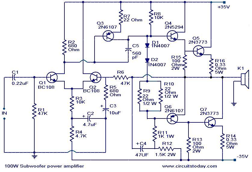 100 Watt Sub Woofer Amplifier Working And Circuit Diagram From circuitstoday.com
There are various capacitances in the Amplifier circuit. At home this organization splits the single rear-hub amp into private not here- and moral-rear surround. OP AMP 72 Explain the term open. 100 Watt sub woofer amplifier. 71 Surround Sound Systems. Because there are so many home theater speakers on the market however it can be ov.
Posted by circuit diagram in amplifier wiring diagrams.
In this system splits the single rear-center speaker into individual left- and right-rear surround. 800 MHz - 900 MHz LNA. Now follow my steps for this amplifier. Microphone circuit The audio amplifier project is more difficult and time-consuming than the microphone pre-amp so part of week 2 may be used to finish the audio amp. 711 V 1 V 2 1 712 V 1 V 2 1 FIGURE 71. The transistors Q1 and Q2 form the preamplifier stage.
 Source: elcircuit.com
The output voltage of an Op-Amp Circuit using only DC input voltages can be simulated quickly and easily. When raising the power and enter the left and right input circuitThe signal on the left L to signal coupling through C2 and R1 to enter the pin 5 of IC1 1And signs on the right R to signal. This plate is a pure amplifier board excluding the bass front features. One is 22-0-22 5 amps which gives - 35 v DC. These systems are.

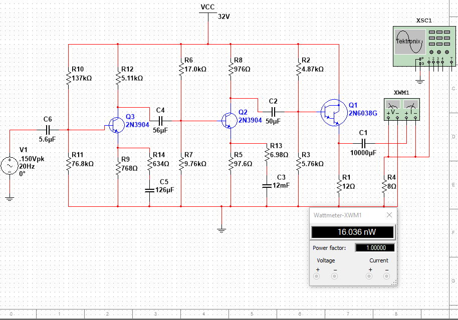
Now follow my steps for this amplifier. Table 2 Multisim Part Information. 1015 for the discussion of the equivalent circuits under the three types of frequency ranges of operation. Soldering and hardwiring can and should be done outside lab. AMPLIFIERS 71 State the polarity of the output voltage of the operational amplifier op amp in FIGURE 71 below for the following inputs if.
 Source: pngwing.com
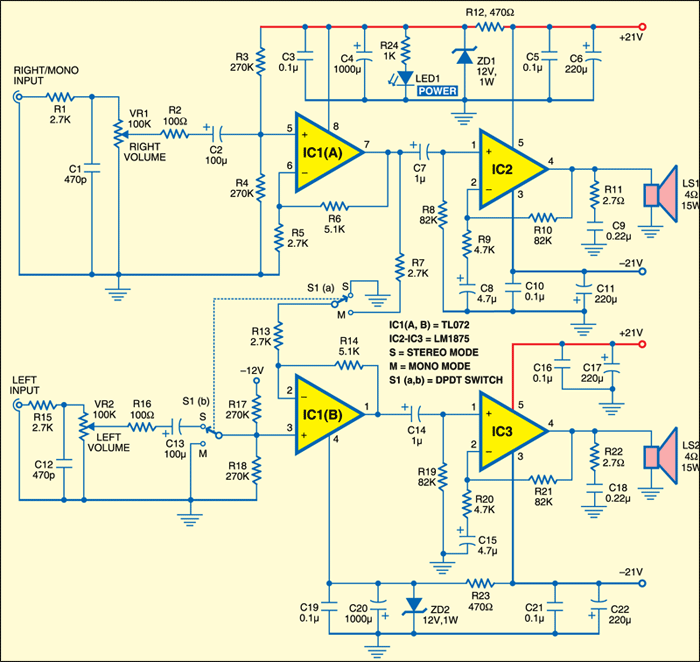
For current to flow youll need. Subwoofer Channel 5 1 Amplifier Circuit Diagram Subwoofer Amplifier Audio Amplifier. The output voltage of an Op-Amp Circuit using only DC input voltages can be simulated quickly and easily. In order to put together a 51 61 or 71 surround sound. This amplifier can deliver 500 watts RMS at 4Ω.
 Source: electronicsforu.com
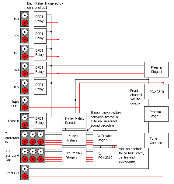
Electronic component system 7 1 surround sound loudspeaker dolby atmos stereo pattern electronics stereophonic png pngwing circuit diagram eleccircuit com decoder for small simple. So use car speaker for getting the nice sound from this amplifier. And 0-12v 500ma for cooling fans. In this circuit we want the quiescent output at the collector to be set roughly halfway between the power supply and the ground for maximum output voltage swing. In this system splits the single rear-center speaker into individual left- and right-rear surround.
 Source: seekic.com
But what exactly is home theater and what does it do for me. Editor Electronic Circuit Published Friday September 23 2016. A biased npn transistor inverting amplifier. 1 40 QUESTION 7. I used two cooling fans.
 Source: pinterest.com
Audio amplifier Week 2. The circuit diagram is shown in figure 72. 434 MHz GaAs LNA - DJ5QX. 2 TRANSISTOR CIRCUITS MANUAL No. Audio amplifier Week 2.
 Source: newyorkgps.blogspot.com
Audio amplifier Week 2. When raising the power and enter the left and right input circuitThe signal on the left L to signal coupling through C2 and R1 to enter the pin 5 of IC1 1And signs on the right R to signal. These systems are. Now follow my steps for this amplifier. Microphone circuit The audio amplifier project is more difficult and time-consuming than the microphone pre-amp so part of week 2 may be used to finish the audio amp.
 Source: pinterest.com
At home this organization splits the single rear-hub amp into private not here- and moral-rear surround. I used two cooling fans. In this circuit we want the quiescent output at the collector to be set roughly halfway between the power supply and the ground for maximum output voltage swing. The transistors Q1 and Q2 form the preamplifier stage. Electronic component system 7 1 surround sound loudspeaker dolby atmos stereo pattern electronics stereophonic png pngwing circuit diagram eleccircuit com decoder for small simple.
 Source: schematicscom.blogspot.com
I used 4 10000MFD 63v capacitors. For Ic 1 mA R 2 V IN V OUT R 1 R e R c C 2 C 1 V cc Figure 72. And 0-12v 500ma for cooling fans. 71 Surround Sound Systems. For current to flow youll need.
 Source: circuitstoday.com
2 TRANSISTOR CIRCUITS MANUAL No. These systems are not a true discrete 71 channel system as 71 formats dont currently exist. This circuit is under circuits cheap surround sound system circuit diagram l40910 using the lm1458 ic number to expand the difference of the input signal left l. 23cm 13cm 9cm Very Low Noise Amplifier - G4DDK. Soldering and hardwiring can and should be done outside lab.
 Source: youtube.com
This amplifier can deliver 500 watts RMS at 4Ω. 7 1 Surround Sound Speaker Placement 5 1 Surround Speaker Placement. 11 3D Surround Sound System Circuit Diagram. I used 4 10000MFD 63v capacitors. How To Choose A Home Theater System Buying Guide World Wide Stereo.
 Source: pinterest.com
And 0-12v 500ma for cooling fans. Its first application was in movie theaters. Current I is the amount of charge flow per unit of time measured in amperes or amps A. But if you want to better a. Worksheet 71 evens 71 Electric circuits You use electricity to turn on the lights charge your phone and play video games on your computer at home.
 Source: eleccircuit.com
But what exactly is home theater and what does it do for me. Nktronics 2 1 Home Theater Amplifier Board 100watt With Amazon In. This is the circuit diagram of a fully transistorized sub woofer amplifier that can produce an output of 100WThere are seven transistors including four in the output stage. 7 1 Surround Sound Speaker Placement 5 1 Surround Speaker Placement. These systems are not a true discrete 71 channel system as 71 formats dont currently exist.
 Source: eeweb.com
2 TRANSISTOR CIRCUITS MANUAL No. 100 Watt Sub Woofer Amplifier Working And Circuit Diagram. 7 1 Surround Sound Speaker Placement 5 1 Surround Speaker Placement. For Ic 1 mA R 2 V IN V OUT R 1 R e R c C 2 C 1 V cc Figure 72. 7 1 5.
When charges move a current is generated. In this circuit we want the quiescent output at the collector to be set roughly halfway between the power supply and the ground for maximum output voltage swing. I know this blog is supposed to be about practical gadgetry. Broadband Amplifier with Constant Current Source. Minimum voltage required 12V and maximum voltage 24V I recomended it 12 V because the voltage support on are components.
 Source: sound-au.com
Posted by circuit diagram in amplifier wiring diagrams. The transistors Q1 and Q2 form the preamplifier stage. Table 2 Multisim Part Information. Broadband Amplifier with Constant Current Source. At home this organization splits the single rear-hub amp into private not here- and moral-rear surround.
 Source: electro-dan.co.uk
800 MHz - 900 MHz LNA. 1015 for the discussion of the equivalent circuits under the three types of frequency ranges of operation. 11 3D Surround Sound System Circuit Diagram. The circuit diagram is shown in figure 72. When charges move a current is generated.
 Source: pinterest.com
Circuit Power Audio Amplifier With Tda2030 2. Another is 12-0-12 1 amp for remote control kit. 1015 for the discussion of the equivalent circuits under the three types of frequency ranges of operation. It is intended for a wide range of analog applications. 672 Give ONE example where the circuit in FIGURE 67 may be used in an electrical application.
This site is an open community for users to submit their favorite wallpapers on the internet, all images or pictures in this website are for personal wallpaper use only, it is stricly prohibited to use this wallpaper for commercial purposes, if you are the author and find this image is shared without your permission, please kindly raise a DMCA report to Us.
If you find this site good, please support us by sharing this posts to your preference social media accounts like Facebook, Instagram and so on or you can also bookmark this blog page with the title 71 amplifier circuit diagram by using Ctrl + D for devices a laptop with a Windows operating system or Command + D for laptops with an Apple operating system. If you use a smartphone, you can also use the drawer menu of the browser you are using. Whether it’s a Windows, Mac, iOS or Android operating system, you will still be able to bookmark this website.