8237 pin diagram
Home » Background » 8237 pin diagramYour 8237 pin diagram images are ready in this website. 8237 pin diagram are a topic that is being searched for and liked by netizens now. You can Find and Download the 8237 pin diagram files here. Download all royalty-free photos and vectors.
If you’re looking for 8237 pin diagram images information related to the 8237 pin diagram interest, you have pay a visit to the right site. Our website always provides you with hints for downloading the highest quality video and picture content, please kindly search and find more informative video articles and graphics that fit your interests.
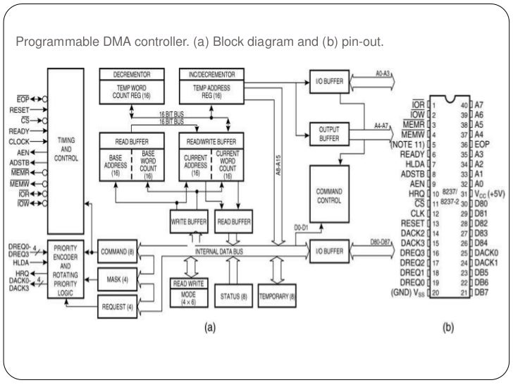
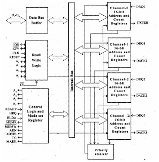
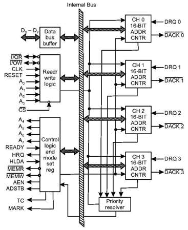
8237 Pin Diagram. In the above figure there are three counters a data bus buffer ReadWrite control logic and a control register. Each channel is conhroller of addressing a full 64k-byte section of memory and can transfer up to 64k bytes with a single programming. The timing and control block priority block and internal registers are the. A Block diagram and b pin-out11 12.

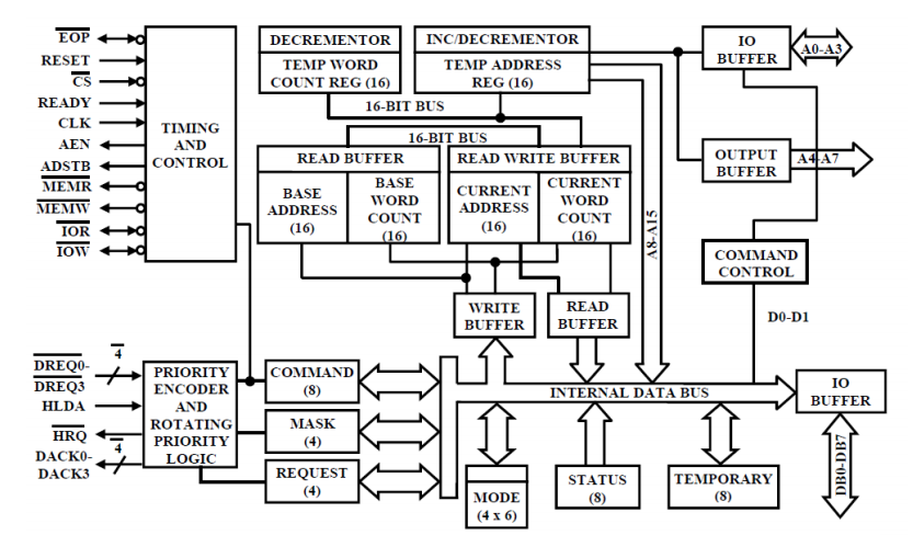
Additionally memory-to-memory bit DMA would require use of channel 4 conflicting with its use to cascade the that handles the 8. The block diagram shows a logical pin out and internal registers of the 8237. The peripheral connected to the highest priority channel is acknowledged. Retrieved from https. DMA controller needs the same old circuits of an interface to communicate with the CPU and InputOutput devices. It also shows the interface with the 8085 using a 3-to-8 decoder 8237 has four independent channels CH0-CH3.
Each channel has its own current address register for this purpose.
They may act as either output latches or. Block Diagram of 8237. Direct memory access with DMA controller 82578237 Last Updated. Each channel is dedicated to a specific peripheral device and. 8237 Internal RegistersCAR The current address register holds a 16-bit memory address used for the DMA transfer. In the above figure there are three counters a data bus buffer ReadWrite control logic and a control register.
 Source: deeprajbhujel.blogspot.com
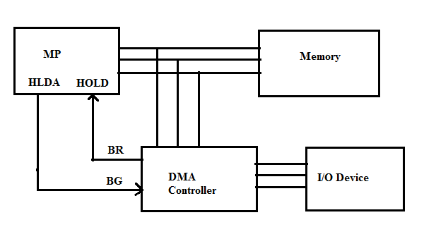
Fig-1 below shows the block diagram of the DMA controller. Here is the pin diagram of 8254. Additionally memory-to-memory bit DMA would require use of channel 4 conflicting with its use to cascade the that handles the 8. Fig-1 below shows the block diagram of the DMA controller. DMA controller needs the same old circuits of an interface to communicate with the CPU and InputOutput devices.
 Source: es.slideshare.net
The input may be driven at up to 5 MHz for the 8237A-5. Each channel has its own current address register for this purpose. PIN Diagram Intel 8237. CLK I CLOCK INPUT. The latter interfaces directly to thebut the has a bit address bus.

It enables data transfer between memory and the IO with reduced load on the systems main processor by providing the memory with control signals and memory address information during the DMA transfer. Pin Configuration 2314661 Figure 1. They may act as either output latches or. The block diagram of the 82C37A is shown in Fig166. Each counter has two input signals - CLOCK GATE and one output signal - OUT.

Retrieved from https. Block Diagram of 8237. The latter interfaces directly to thebut the has a bit address bus. The 8237 DMA controller supplies the memory and IO with control signals and memory address information during the DMA transfer. The block diagram of the 82C37A is shown in Fig166.
 Source: scanftree.com
The latter interfaces directly to thebut the has a bit address bus. Block Diagram of 8237. Each channel has its own current address register for this purpose. DMA controller commonly used with 8088 is the 8237 programmable device. Clock Input controls the internal operations of the 8237A and its rate of data transfers.
 Source: youtube.com
Selection of ports 462021 6. Like the firstit is augmented with four address-extension registers. 2 Pin Diagram of 8255. In the above figure there are three counters a data bus buffer ReadWrite control logic and a control register. 8237 Internal RegistersCAR The current address register holds a 16-bit memory address used for the DMA transfer.
 Source: tutorialspoint.com
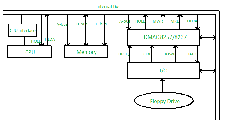
132 THE 8237 DMA CONTROLLER The 8237 supplies memory IO with control signals and memory address information during the DMA transfer. 132 THE 8237 DMA CONTROLLER The 8237 supplies memory IO with control signals and memory address information during the DMA transfer. The signal description of 8255 are briefly presented as follows. The 8237 is in fact a special-purpose microprocessor. Direct Memory Access DMA.

Block Diagram of 8237. 17 May 2021 Suppose any device which is connected at input-output port wants to transfer data to transfer data to memory first of all it will send input-output port address and control signal input-output read to input-output port then it will send memory address and memory. Functional Description The 82C37A direct memory access controller is designed to improve the data. The timing and control block priority block and internal registers are the. Direct Memory Access DMA.
 Source: citgetit.blogspot.com
8237 Direct memory Access Controller DMAC 8255- PPI 462021 4 82C55 programmable peripheral interface PPI is a. The block diagram shows a logical pin out and internal registers of the 8237. The block diagram of the 82C37A is shown in Fig166. Clock Input controls the internal operations of the 8237A and its rate of data transfers. Retrieved from https.
 Source: slidetodoc.com
The 8237 is a 4-channel device. The latter interfaces directly to thebut the has a bit address bus. Each channel is conhroller of addressing a full 64k-byte section of memory and can transfer up to 64k bytes with a single programming. It enables data transfer between memory and the IO with reduced load on the systems main processor by providing the memory with control signals and memory address information during the DMA transfer. Retrieved from https.
 Source: geeksforgeeks.org
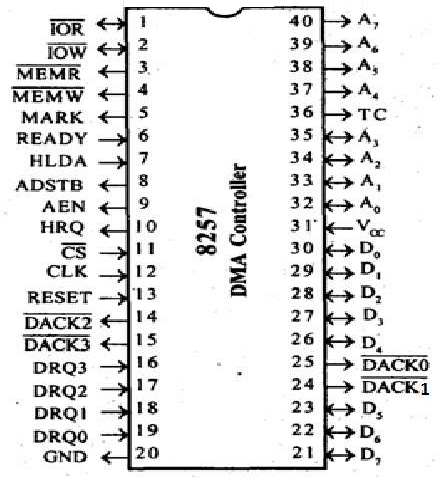
Like the firstit is augmented with four address-extension registers. The following image shows the pin diagram of a 8257 DMA controller. Pin Configuration 2314661 Figure 1. 8237 Internal RegistersCAR The current address register holds a 16-bit memory address used for the DMA transfer. The peripheral connected to the highest priority channel is acknowledged.
 Source: youtube.com
8237 Direct memory Access Controller DMAC 8255- PPI 462021 4 82C55 programmable peripheral interface PPI is a. Pin Diagram of 8255 462021 5. CLOCK INPUTClock Input controls the internal operations of the 8237A and its rate of data transfers. It is the low memory read signal which is used to read the data from the addressed memory locations during DMA read cycles. DMA Controller is a hardware device that allows IO devices to directly access memory with less participation of the processor.
 Source: tutorialspoint.com
The 8237 is in fact a special-purpose microprocessor. Block Diagram of 8237. The input may be driven at up. 132 THE 8237 DMA CONTROLLER The 8237 supplies memory IO with control signals and memory address information during the DMA transfer. Direct Memory Access DMA.
 Source: slidetodoc.com
The 8237 is in fact a special-purpose microprocessor. The 8237 is in fact a special-purpose microprocessor. Here is the pin diagram of 8254. In the above figure there are three counters a data bus buffer ReadWrite control logic and a control register. 17 May 2021 Suppose any device which is connected at input-output port wants to transfer data to transfer data to memory first of all it will send input-output port address and control signal input-output read to input-output port then it will send memory address and memory.
 Source: en.wikipedia.org
In the above figure there are three counters a data bus buffer ReadWrite control logic and a control register. 8237 System Interface Write a control word in the mode register that select the channel and specify the type of transfer readwrite or verify and the DMA mode block single byte etc. Each channel is dedicated to a specific peripheral device and capable of addressing 64 K bytes section of memory. Block Diagram of 8237. When paired with single Intel 8212 IO port device the 8257 DMA controller forms a complete 4 channel DMA controller.
 Source: elprocus.com
The 8237 Architecture. 17 May 2021 Suppose any device which is connected at input-output port wants to transfer data to transfer data to memory first of all it will send input-output port address and control signal input-output read to input-output port then it will send memory address and memory. The 8237 is a 4-channel device. PIN DIAGRAM KNCET EEE DEPARTMENT 3. DMA controller commonly used with 8088 is the 8237 programmable device.
 Source: scanftree.com
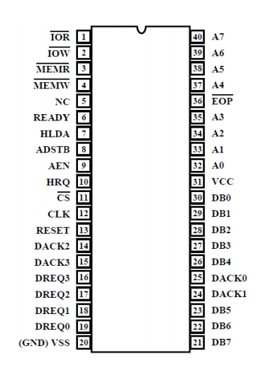
DRQ 0 to DRQ 3 Pin number 16 to 19 These pins get enabled whenever the input device requests the DMA controller for direct data transfer to or from the main memory. The 8237 is in fact a special-purpose microprocessor. Selection of ports 462021 6. In the above figure there are three counters a data bus buffer ReadWrite control logic and a control register. 8237 Internal RegistersCAR The current address register holds a 16-bit memory address used for the DMA transfer.
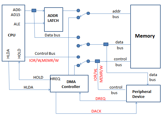 Source: scanftree.com
8237 Internal RegistersCAR The current address register holds a 16-bit memory address used for the DMA transfer. CLOCK INPUTClock Input controls the internal operations of the 8237A and its rate of data transfers. DMA CONTROLLER It is a device that can control data transfer between an IO subsystem and a memory subsystem without help of the CPU DMA OPERATIONS. The 8237 Architecture. The 8237 is in fact a special-purpose microprocessor.
This site is an open community for users to do sharing their favorite wallpapers on the internet, all images or pictures in this website are for personal wallpaper use only, it is stricly prohibited to use this wallpaper for commercial purposes, if you are the author and find this image is shared without your permission, please kindly raise a DMCA report to Us.
If you find this site value, please support us by sharing this posts to your favorite social media accounts like Facebook, Instagram and so on or you can also bookmark this blog page with the title 8237 pin diagram by using Ctrl + D for devices a laptop with a Windows operating system or Command + D for laptops with an Apple operating system. If you use a smartphone, you can also use the drawer menu of the browser you are using. Whether it’s a Windows, Mac, iOS or Android operating system, you will still be able to bookmark this website.