89c2051 programmer circuit diagram
Home » Background » 89c2051 programmer circuit diagramYour 89c2051 programmer circuit diagram images are ready. 89c2051 programmer circuit diagram are a topic that is being searched for and liked by netizens today. You can Get the 89c2051 programmer circuit diagram files here. Get all royalty-free photos.
If you’re looking for 89c2051 programmer circuit diagram pictures information linked to the 89c2051 programmer circuit diagram topic, you have come to the right site. Our website always gives you hints for seeking the highest quality video and picture content, please kindly hunt and find more informative video content and images that fit your interests.
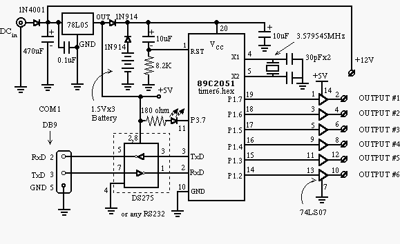
89c2051 Programmer Circuit Diagram. 89C2051 Programmer Other Resources. In order to create a programmer I must have one ready. Here comes the problem. Connect the circuit as per the fig 2.
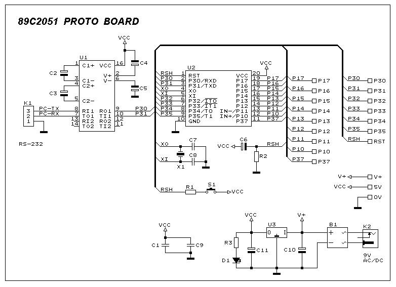 Atmel 89c2051 Prototype Board Under Repository Circuits 45329 Next Gr From next.gr
All the programmers I have seen used a pre programmed AT89C2051 of 89C51 chip. Figure 1 shows a circuit diagramof the Easy-Downloader. There are 2778 circuit schematics available. Open the OpenProgexe and check the device connected. Firmware 2 is working for 89c52 and 89s52 tested. Atmel 89C2051 In-Circuit Programmer Schematic This is a beta release schematic.
Following uJDM PIC programmer circuit is a circuit which suitable to do simple pic16f84 pic16f84A 16c84 16f628 group programmer.
Posted by Margaret Byrd Posted on September 28 2017. Following uJDM PIC programmer circuit is a circuit which suitable to do simple pic16f84 pic16f84A 16c84 16f628 group programmer. I wanted a programmer for AT89C2051 or for At89CXX. MSP430f149 prepared for the parallel port JTAG Programmer circuit of the circuit diagram pcb protel and pdfs. Here comes the problem. RS232 24CXX Series eeprom Programmer Circuit PCB.
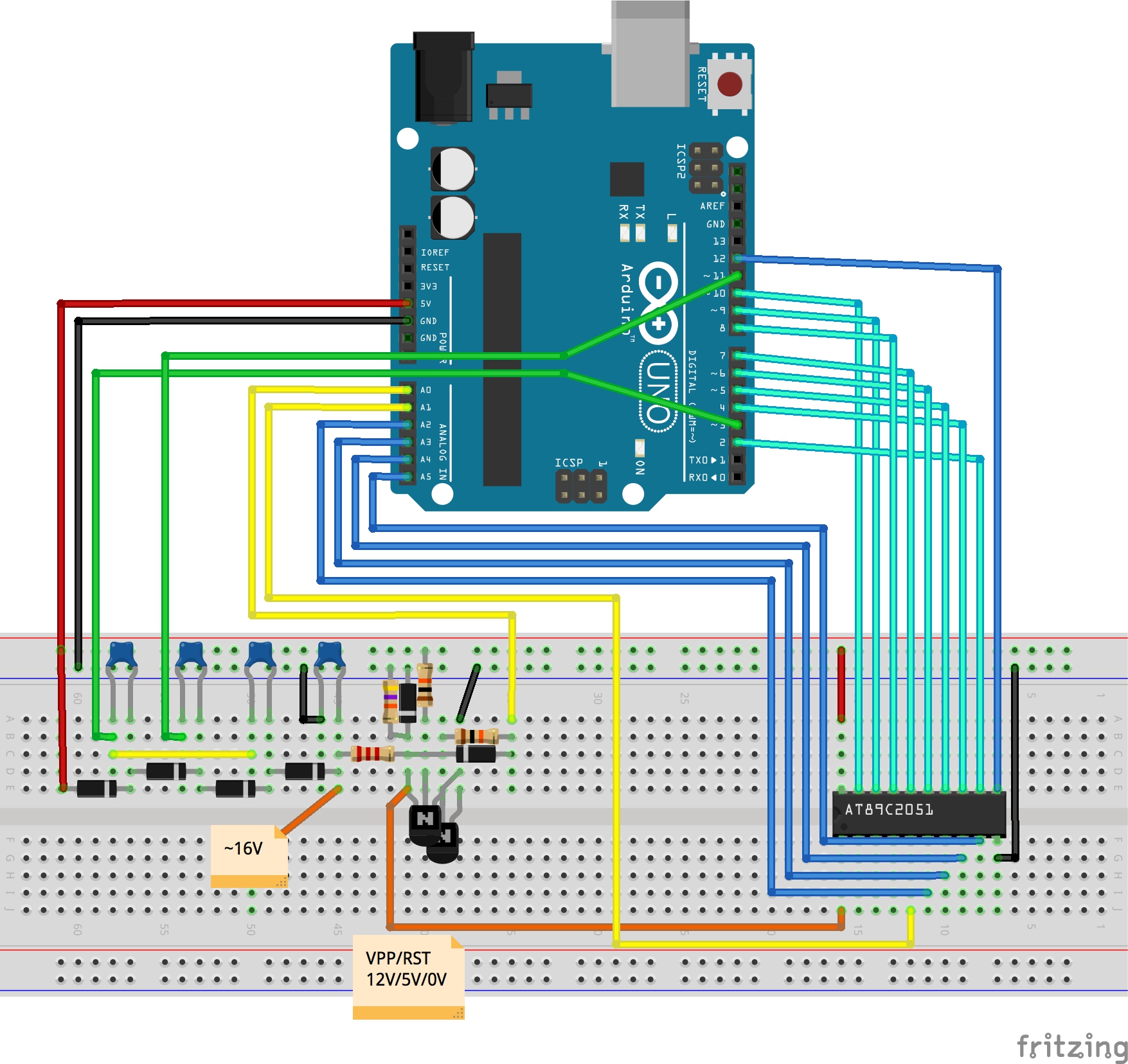 Source: leap.tardate.com
If the programmer is detected go to next step. 8051 Development System Circuit. Posted by Margaret Byrd Posted on September 28 2017. The circuit schematic diagram is shown in Figure 2. While the circuit diagram specifies 3v45v battery the part ULN2803 needs 45v-5v battery to get proper operation.
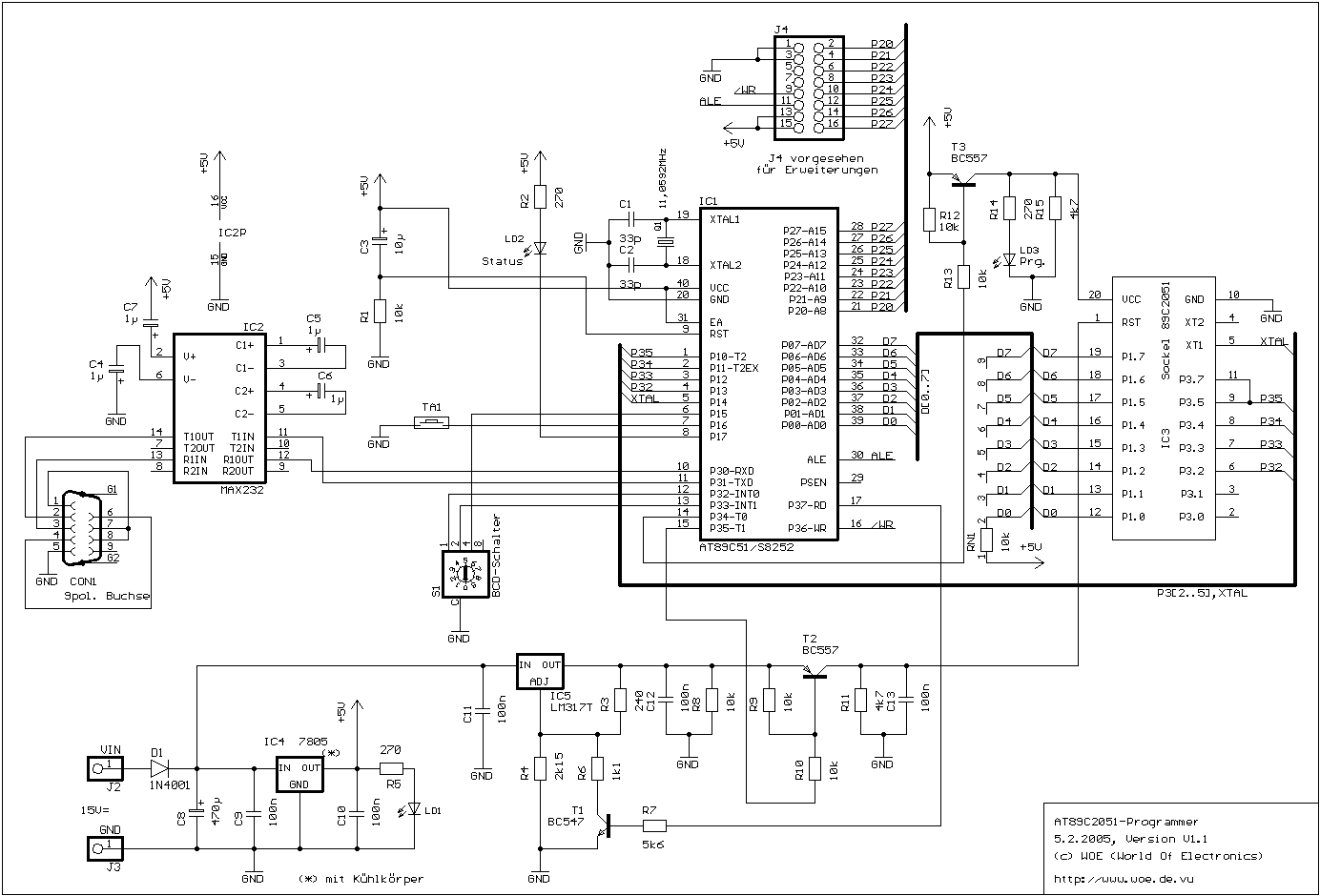 Source: small-electronic-projects.blogspot.com
The programming voltage control circuit is the. Here comes the problem. The circuit schematic diagram is shown in Figure 2. Connect the circuit as per the fig 2. Thus by varying the delay after which the TRIAC is triggered one can change the speed of motor.
 Source: small-electronic-projects.blogspot.com
Open the OpenProgexe and check the device connected. Assemble the circuit and burn the firmware into an AT89C2051 you will need a conventional parallel Programmer to Program the AT89C2051. I wanted a programmer for AT89C2051 or for At89CXX. Line Follower Robot Program. The controller is composed of regulated power supply circuit PWM generation circuit motor drive circuit battery discharge indication circuit motor over-current and battery over discharge protection circuit.

All the programmers I have seen used a pre programmed AT89C2051 of 89C51 chip. A newer version Rev 4. Thus by varying the delay after which the TRIAC is triggered one can change the speed of motor. K182A - USB ICSP Flash Pic Programmer. Home Electronic Tutorials Microcontroller Based Schematics Atmel 89C2051 prototype board circuit.
 Source: next.gr
A newer version Rev 4. Following uJDM PIC programmer circuit is a circuit which suitable to do simple pic16f84 pic16f84A 16c84 16f628 group programmer. Thus by varying the delay after which the TRIAC is triggered one can change the speed of motor. Atmel avr and 8051 series isp flash programmer ver 3 0 at89s51 52 erase based microcontroller 89c2051 in circuit for 89c51 55 89s51 page. As shown the circuit uses a 89C2051 with writerhex firmware 74LS373 8-bit latch DS275-like 7805 LM317 and two transistors 2N2222A and 2N2907A.
 Source: skieyonestop.weebly.com
Open the OpenProgexe and check the device connected. Here AT89C2051 is loaded with firmware required for RS232 communication with PC. Assemble the circuit and burn the firmware into an AT89C2051 you will need a conventional parallel Programmer to Program the AT89C2051. Use at your own risk The idea is to add this circuitry to a board with already has ram at 2000 and an 82C55 IO chip to provide ports A B and C. Atmel avr and 8051 series isp flash programmer ver 3 0 at89s51 52 erase based microcontroller 89c2051 in circuit for 89c51 55 89s51 page.
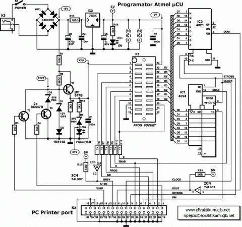 Source: embedded-lab.com
Not shown here is a memory mapping trick which is described below. 89c2051 4051 programmer atmel at89c2051 hardware keylogers in circuit driving dot led leap 394 a simple parallel port for based electronic dice avr at89c4051 usb remote controlled smartfan using prototype board. Switch SW2 allows the PCB to be turned on. The battery power supply is connected on terminals T1 T2. K75 - Intro PIC Trainer w Temp Timer Counter AD.
 Source: radanpro.com
Could not able to work with 89c2051. If the programmer is detected go to next step. Here AT89C2051 is loaded with firmware required for RS232 communication with PC. Use the 40 pin ZIF socket for microcontrollerThe firmwareHEX file is in the Software folder. Figure 1 shows a circuit diagramof the Easy-Downloader.
 Source: 51c51.com
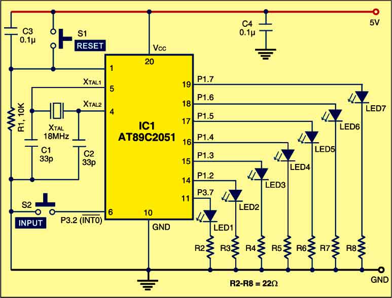
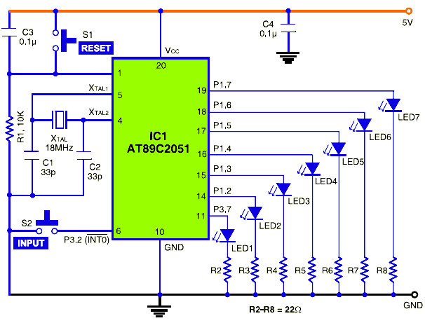
I want a circuit without pre programmed chip or a circuit having 89Sxx as preprogrammed chip. Use the 40 pin ZIF socket for microcontrollerThe firmwareHEX file is in the Software folder. After getting an interrupt 89C51 will fire TRIAC after some delay from 1 to 9 ms. Switch S1 capacitor C3 and resistor R9 forms a debouncing reset circuit for the microcontroller. The controller is composed of regulated power supply circuit PWM generation circuit motor drive circuit battery discharge indication circuit motor over-current and battery over discharge protection circuit.
 Source: next.gr
8051 Flash Programmer Circuit Diagram. 8051 Flash Programmer Circuit Diagram. While the circuit diagram specifies 3v45v battery the part ULN2803 needs 45v-5v battery to get proper operation. There are 2778 circuit schematics available. The programming voltage control circuit is the.
 Source: electronicsforu.com
New Rev 4 Board. Capacitors C1 C2 and 12MHz crystal X1 are associated with the microcontrollers clock circuit. R12 and R13 are pull-up resistors. Figure 1 depicts a circuit diagram of the Easy-Downloader. The circuit schematic diagram is shown in Figure 2.
 Source: hobbyprojects.com
Open the OpenProgexe and check the device connected. Assemble the circuit and burn the firmware into an AT89C2051 you will need a conventional parallel Programmer to Program the AT89C2051. Use the 40 pin ZIF socket for microcontrollerThe firmwareHEX file is in the Software folder. A newer version Rev 4. This will cut the current supplied to motor and so the speed of motor will reduce.
 Source: 320volt.com
Here AT89C2051 is loaded with firmware required for RS232 communication with PC. Use at your own risk The idea is to add this circuitry to a board with already has ram at 2000 and an 82C55 IO chip to provide ports A B and C. MSP430f149 prepared for the parallel port JTAG Programmer circuit of the circuit diagram pcb protel and pdfs. MSP430f149 JTAG schematic pcb. Capacitors C1 C2 and 12MHz crystal X1 are associated with the microcontrollers clock circuit.
 Source: circuitscheme.com
If the programmer is not detected cross check the connections and the instructions. Generate video signals in real-time using a PIC16F84 Schematics wiring diagram circuits schema electronic projects. Check the blinking of LED1 is flashing firstly at first and then it slows the blink. Electric forklift controller circuit diagram 1 1 Circuit principle. Use the 40 pin ZIF socket for microcontrollerThe firmwareHEX file is in the Software folder.
 Source: researchgate.net
Thus by varying the delay after which the TRIAC is triggered one can change the speed of motor. Is there any other difference. Circuit diagram The circuit diagram is pictured above. Remaining sections of the circuit were explained already. Figure 1 shows a circuit diagramof the Easy-Downloader.
 Source: radanpro.com
All the programmers I have seen used a pre programmed AT89C2051 of 89C51 chip. Use the 40 pin ZIF socket for microcontrollerThe firmwareHEX file is in the Software folder. Use the 40 pin ZIF socket for microcontrollerThe firmwareHEX file is in the Software folder. I wanted a programmer for AT89C2051 or for At89CXX. Microcontroller Based Schematics Projects Tutorials.
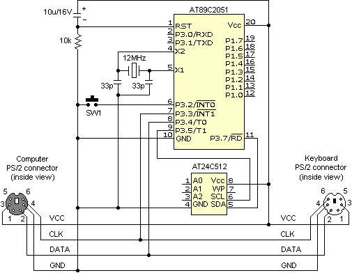 Source: 320volt.com
The battery power supply is connected on terminals T1 T2. The Last circuit was added on Saturday August 21 2021Please note some adblockers will suppress the schematics as well as the advertisement so please disable if the schematic list is empty. Figure 1 shows a circuit diagram of the Easy-Downloader. After getting an interrupt 89C51 will fire TRIAC after some delay from 1 to 9 ms. The programming voltage control circuit is the.
 Source: ceptimus.co.uk
This is a very simple application of a single chip microprocessor IC1. Circuit diagram The circuit diagram is pictured above. As shown the circuit uses a 89C2051 with writerhex firmware 74LS373 8-bit latch DS275-like 7805 LM317 and two transistors 2N2222A and 2N2907A. Microcontroller Based Schematics Projects Tutorials. K182A - USB ICSP Flash Pic Programmer.
This site is an open community for users to share their favorite wallpapers on the internet, all images or pictures in this website are for personal wallpaper use only, it is stricly prohibited to use this wallpaper for commercial purposes, if you are the author and find this image is shared without your permission, please kindly raise a DMCA report to Us.
If you find this site beneficial, please support us by sharing this posts to your own social media accounts like Facebook, Instagram and so on or you can also save this blog page with the title 89c2051 programmer circuit diagram by using Ctrl + D for devices a laptop with a Windows operating system or Command + D for laptops with an Apple operating system. If you use a smartphone, you can also use the drawer menu of the browser you are using. Whether it’s a Windows, Mac, iOS or Android operating system, you will still be able to bookmark this website.