8x3 encoder circuit diagram
Home » Background » 8x3 encoder circuit diagramYour 8x3 encoder circuit diagram images are ready. 8x3 encoder circuit diagram are a topic that is being searched for and liked by netizens now. You can Find and Download the 8x3 encoder circuit diagram files here. Find and Download all free photos and vectors.
If you’re searching for 8x3 encoder circuit diagram images information linked to the 8x3 encoder circuit diagram keyword, you have pay a visit to the ideal blog. Our website frequently provides you with hints for viewing the highest quality video and image content, please kindly search and find more informative video content and images that match your interests.
8x3 Encoder Circuit Diagram. The input becomes output and vice versa. The output of a priority encoder is the binary representation of the. Encoder Circuit Electrical Diagram size. Or you are a trainee or perhaps even you who simply would like to know concerning Encoder Circuit Diagram.
 Encoder Techtud From techtud.com
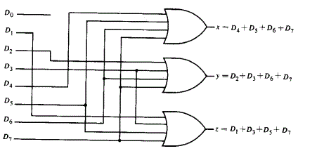
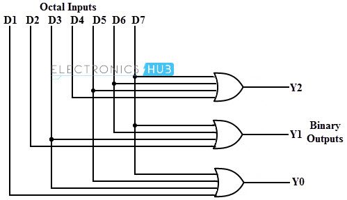
What is an encoder. The input becomes output and vice versa. Here in the given figure one case is highlighted when D7 input is 1 all outputs a 1 b1. The above circuit diagram contains two OR gates. Encoder is a combinational circuit which converts set of signal into equivalent code. If you applied 0 through 3 to one of these logic circuits and inputs 4 through 7 to the other logic circuit.
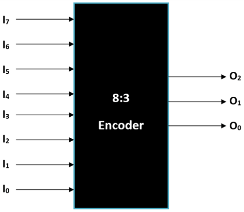
In other words an encoder is a circuit in which output lines generate the binary code corresponding to the input value.
It is convenient to use an AND gate as the basic decoding element for the output because it produces a HIGH or logic 1 output only when all of its inputs are logic 1. The circuit diagram of 4 to 2 priority encoder is drawn with 2 OR gates and the combination of AND gate and the NOT gate represent the valid bit which is used when more than one input is logic high 1. 3 to 8 Decoder. Thus four inputs with two outputs are encoded based on the assigned priority to the inputs. Based on the 3 inputs one of the eight outputs is selected. What is an encoder.
 Source: geeksforgeeks.org
3 to 8 line Decoder has a memory of 8 stages. VHDL program Simulation waveforms As shown in the figure the input-output waveforms look similar to the decoder because the encoder is just the reverse of the decoder. From the truth table it is seen that only. At first check the Display and mark every abcdefg terminal as per the circuit diagram. 1 to 8 Demux circuit 3 to 8 DecoderDemultiplexer.
 Source: geeksforgeeks.org
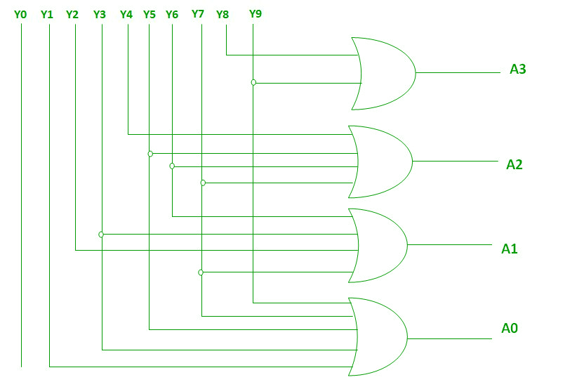
3 to 8 Decoder and truth table of 3 to 8 decoder. The circuit uses a 4-input OR gate IC you can also simplify the Boolean Expression to use other normal 2 input Gate ICs. An Encoder is a combinational circuit that performs the reverse operation of DecoderIt has maximum of 2n input lines and n output lines hence it encodes the information from 2n inputs into an n-bit codeIt will produce a binary code equivalent to the input which is active High. 4 to 2 Priority Encoder Circuit Diagram. The circuit diagram of the 1 to 8 demux circuit is shown below.
 Source: electricaltechnology.org
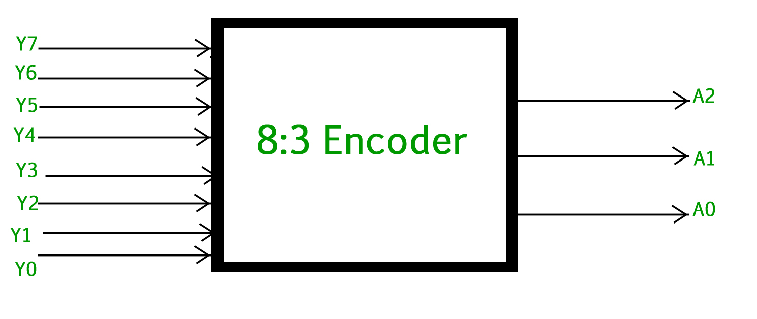
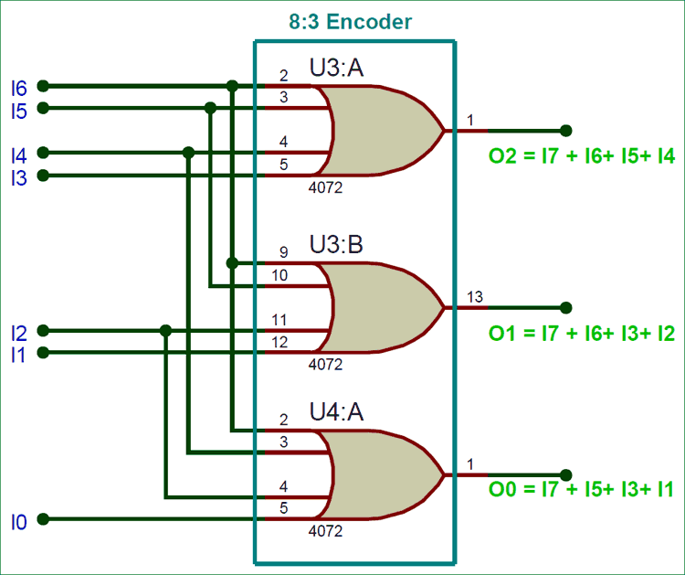
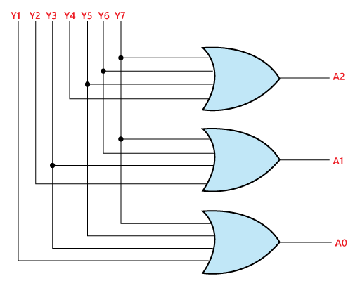
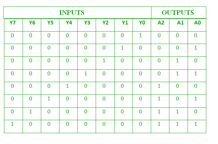
In simple terms an encoder takes in 2n binary inputs one at a time and codes them into n bits of one output code. 3 to 8 line decoder IC 74HC238 is used as a decoder demultiplexer. At first check the Display and mark every abcdefg terminal as per the circuit diagram. The circuit diagram of the 1 to 8 demux circuit is shown below. In 8 to 3 line encoder there is a total of eight inputs ie Y 0 Y 1 Y 2 Y 3 Y 4 Y 5 Y 6 and Y 7 and three outputs ie A 0 A1 and A 2.
 Source: circuitdigest.com
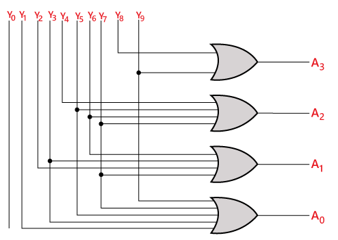
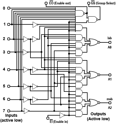
Function is exactly opposite of DecoderFind out Test Bench for 8x3 Encoder here. The circuit diagram of 4 to 2 encoder is shown in the following figure. An IC 74148 is the most popularly used MSI encoder circuits for the 8 to 3 line priority encoder. Here in the given figure one case is highlighted when D7 input is 1 all outputs a 1 b1. Therefore the encoder encodes 2n input lines with n bits.
 Source: javatpoint.com
In 8 to 3 line encoder there is a total of eight inputs ie Y 0 Y 1 Y 2 Y 3 Y 4 Y 5 Y 6 and Y 7 and three outputs ie A 0 A1 and A 2. 4 to 2 Priority Encoder Circuit Diagram. The circuit diagram of 4 to 2 encoder is shown in the following figure. If input n is active all lower inputs n-1. An Encoder is a combinational circuit that performs the reverse operation of DecoderIt has maximum of 2n input lines and n output lines hence it encodes the information from 2n inputs into an n-bit codeIt will produce a binary code equivalent to the input which is active High.
 Source: youtube.com
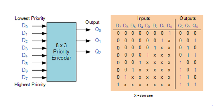
The input becomes output and vice versa. Aim- To study and implement 16x4 priority encoder using 8x3 priority encoder Apparatus- 1 Trainer kit 2 Patch chords 3 Power supply Theory- A priority encoder is a circuit or algorithm that compresses multiple binary inputs into a smaller number of outputs. Octal To Binary Encoder. That is odd to me but your truth table is a generic 83 priority encoder not following the priority list you provided. Here in the given figure one case is highlighted when D7 input is 1 all outputs a 1 b1.
 Source: researchgate.net
An octal to binary encoder has 2 3 8 input. An Encoder is a combinational circuit that performs the reverse operation of DecoderIt has maximum of 2n input lines and n output lines hence it encodes the information from 2n inputs into an n-bit codeIt will produce a binary code equivalent to the input which is active High. 2349 8 8 silver badges 17 17 bronze badges endgroup 1 begingroup Ok. 3 to 8 Decoder and truth table of 3 to 8 decoder. 8 to 3 line Encoder.
 Source: learnabout-electronics.org
It is convenient to use an AND gate as the basic decoding element for the output because it produces a HIGH or logic 1 output only when all of its inputs are logic 1. After making the circuit diagram connect Vcc and GND to the 5V DC supply and start giving the inputs. The logical diagram of the 38 line decoder is given below. 83 encoder circuit. The circuit diagram of 4 to 2 priority encoder is drawn with 2 OR gates and the combination of AND gate and the NOT gate represent the valid bit which is used when more than one input is logic high 1.
 Source: javatpoint.com
In 8 to 3 line encoder there is a total of eight inputs ie Y 0 Y 1 Y 2 Y 3 Y 4 Y 5 Y 6 and Y 7 and three outputs ie A 0 A1 and A 2. Octal To Binary Encoder. The problem with the truth table is that Im not able to create a kv diagram with 8 variables. You are right below. So 4 to 2 priority encoder circuit diagrams using OR NOT AND logic gates.
 Source: techtud.com
Therefore the encoder encodes 2n input lines with n bits. 800 x 600 px source. In simple terms an encoder takes in 2n binary inputs one at a time and codes them into n bits of one output code. Function is exactly opposite of DecoderFind out Test Bench for 8x3 Encoder here. Im trying to implement a 8 to 3 priority encoder which worked quiet well.
 Source: electronicshub.org
4 to 2 Priority Encoder Circuit Diagram. 3 to 8 Decoder and truth table of 3 to 8 decoder. If input n is active all lower inputs n-1. The circuit diagram of the 1 to 8 demux circuit is shown below. 8 to 3 line Encoder.
 Source: electronics-tutorials.ws
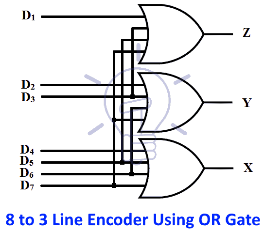
Octal to binary encoder is nothing but 8 to 3 encoder. 2349 8 8 silver badges 17 17 bronze badges endgroup 1 begingroup Ok. An octal to binary encoder has 2 3 8 input. This circuit should not be expected to encode an undefined combination of inputs so we can leave them as dont care when we design the. 3 to 8 line Decoder has a memory of 8 stages.
 Source: circuitdigest.com
Construct a 16 to 1 line MUX with two 8. 3 to 8 Decoder and truth table of 3 to 8 decoder. As it is a 3 to 8 Decoder circuit you. You might be a professional who wishes to look for recommendations or resolve existing issues. So 4 to 2 priority encoder circuit diagrams using OR NOT AND logic gates.
 Source: electronics-tutorials.ws
An Encoder is a combinational circuit that performs the reverse operation of DecoderIt has maximum of 2n input lines and n output lines hence it encodes the information from 2n inputs into an n-bit codeIt will produce a binary code equivalent to the input which is active High. In other words an encoder is a circuit in which output lines generate the binary code corresponding to the input value. However in a simple encoder only one of the inputs is considered to be high out of all the 2n inputs. The input becomes output and vice versa. Lessons In Electric Circuits – Volume IV Digital - Chapter 9.
 Source: teachics.org
Follow answered May 14 17 at 2243. The 74LS148 IC has a wide range of working voltage a wide range of working conditions and directly interfaces with CMOS NMOS and TTL. Written 23 years ago by teamques10 92k. What is an encoder. However in a simple encoder only one of the inputs is considered to be high out of all the 2n inputs.
 Source: caramesin.com
After making the circuit diagram connect Vcc and GND to the 5V DC supply and start giving the inputs. The 8 to 3 line Encoder is also known as Octal to Binary Encoder. Here in the given figure one case is highlighted when D7 input is 1 all outputs a 1 b1. 3 to 8 line Decoder has a memory of 8 stages. An encoder has 2 n or fewer input lines only one of which is in the 1 state at a particular time and an n-bit code is generated on n output lines depending upon which of the input is excited.
 Source: studytronics.weebly.com
Like normal encoder expressions this type of encoder expression is also the same however there is a statement like Y 1 for input D1 simply when D2 input is low because according to the truth table for D2 1 then Y must be 0. 74LS148 8 To 3 Line Priority Encoder IC Datasheet. 3 to 8 Decoder. 3 to 8 line decoder IC 74HC238 is used as a decoder demultiplexer. VHDL program Simulation waveforms As shown in the figure the input-output waveforms look similar to the decoder because the encoder is just the reverse of the decoder.

In 8 to 3 line encoder there is a total of eight inputs ie Y 0 Y 1 Y 2 Y 3 Y 4 Y 5 Y 6 and Y 7 and three outputs ie A 0 A1 and A 2. An encoder is a combinational logic circuit that can be used to convert 2n lines of digital input into n bits of coded binary output. An encoder has 2 n or fewer input lines only one of which is in the 1 state at a particular time and an n-bit code is generated on n output lines depending upon which of the input is excited. 83 Encoder Circuit Diagram. Or you are a trainee or perhaps even you who simply would like to know concerning Encoder Circuit Diagram.
This site is an open community for users to do sharing their favorite wallpapers on the internet, all images or pictures in this website are for personal wallpaper use only, it is stricly prohibited to use this wallpaper for commercial purposes, if you are the author and find this image is shared without your permission, please kindly raise a DMCA report to Us.
If you find this site serviceableness, please support us by sharing this posts to your favorite social media accounts like Facebook, Instagram and so on or you can also bookmark this blog page with the title 8x3 encoder circuit diagram by using Ctrl + D for devices a laptop with a Windows operating system or Command + D for laptops with an Apple operating system. If you use a smartphone, you can also use the drawer menu of the browser you are using. Whether it’s a Windows, Mac, iOS or Android operating system, you will still be able to bookmark this website.