Anemometer circuit diagram
Home » Wallpapers » Anemometer circuit diagramYour Anemometer circuit diagram images are ready in this website. Anemometer circuit diagram are a topic that is being searched for and liked by netizens now. You can Find and Download the Anemometer circuit diagram files here. Get all free photos.
If you’re searching for anemometer circuit diagram images information linked to the anemometer circuit diagram topic, you have visit the ideal site. Our website frequently gives you suggestions for refferencing the maximum quality video and image content, please kindly hunt and find more enlightening video articles and images that fit your interests.
Anemometer Circuit Diagram. Wireless Anemometer Sensor using SCADA. Fig33 Circuit Diagram of Microcontroller Unit. I cant guarantee much on the accuracy of this circuit but it circuit works quite fine. So u need a.
 Schematic Diagram Of The Anemometer Electronics A Three Stage Pi Download Scientific Diagram From researchgate.net
1 Davis Anemometer and Direction Vane Illustration 1. The flat not twisted cable has 4 conductors. The relationship between thermal impedance of the. I cant guarantee much on the accuracy of this circuit but it circuit works quite fine. The anemometer was going to be at the end of about 25m of cable so I used a separate power supply and isolated it from the Arduino board. Sonic Anemometer Viasala 425.
The circuit diagram is.
Yellow direction excitation This is an excitation pulse sent from the SIM to the anemometer and. So u need a. The term is derived from the Greek word anemos which means wind and is used to describe any wind speed instrument used in meteorologyThe first known description of an anemometer was given by Leon Battista Alberti in 1450. This can be done by measuring the heat loss of the wire which is placed in the fluid stream. Constant current method Hot wire Anemometer. Additionally PWM pulse-width modulation anemometers are.
 Source: mdpi.com
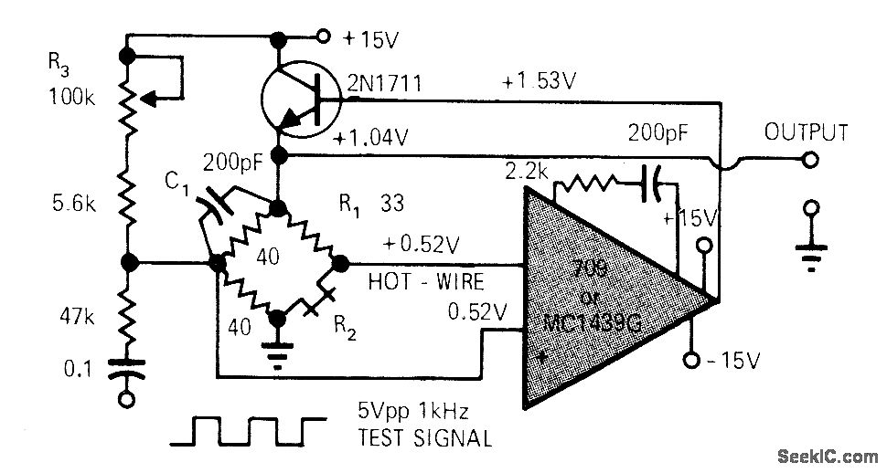
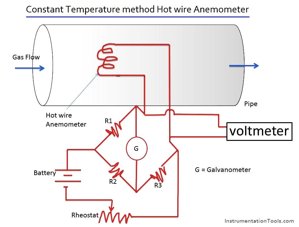
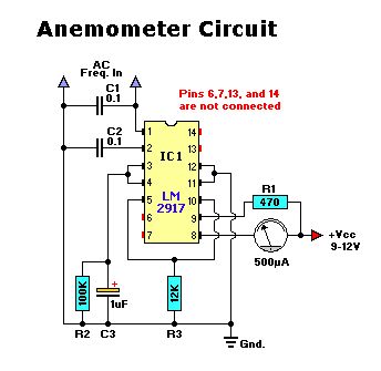
Figure 4 Circuit diagram for wind speed meter The Frequency to Voltage Converter is the major electronic component of this work. Refer to the schematic diagram for the description. Hall effect switch A1120EUA-TThis is a unipolar switch triggered by a south magnetic pole but any hall effect switch should work. The anemometer is kept in the flowing gas stream to measure flow rate. Schematic Diagram Of Hot Wire Anemometer In both these operating modes it is essential to calculate and alter the time constant range of the anemometer.
 Source: seekic.com
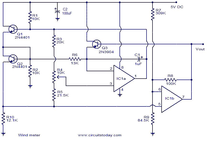
Speed component of the sensor anemometer The use of this design also allows the anemometer to be used in circuits down to zero voltage and current without reducing the life expectancy of the reed switch. The relationship between thermal impedance of the. A complete anemometer before installation. The anemometer must be mounted in an upright position. Here is a very simple wind meter anemometer circuit.
 Source: researchgate.net
Here is a very simple wind meter anemometer circuit. The voltmeter is connected across the bridge circuit to determine the resistance variation from the voltage measurements. The anemometer is kept in the flowing gas stream to measure flow rate. You can measure wind speeds up to 75ms using this circuit. The bridge arrangement along with the anemometer has been shown in diagram.
 Source: researchgate.net
An anemometer is a device used for measuring wind speed and directionIt is also a common weather station instrument. An anemometer is an instrument with metallic hemispheres revolving on a vertical rod used to measure speed of the wind. The circuit diagram of a hot wire anemometer with a constant temperature method is shown below. 2 Anemometer and Direction Vane Circuit Description. 1 Davis Anemometer and Direction Vane Illustration 1.
 Source: instrumentationtools.com
2 Anemometer and Direction Vane Circuit Description. The anemometer is kept in the flowing gas stream to measure flow rate. Installing the anemometer at the. Additionally PWM pulse-width modulation anemometers are. The circuit begins with a 9 VDC supply voltage which is regulated down to a constant 5 VDC by the LM7805 voltage regulator.
 Source: fromindintoconcept.wordpress.com
The mechanical setup of Wind vane IR sensor and 3 cup anemometer is used to measure the direction and speed of the wind. The Block diagram for the device is shown in Fig7. A complete anemometer before installation. The software was implemented using MPLAB. Fig33 Circuit Diagram of Microcontroller Unit.
 Source: circuitstoday.com
As this is completely based on the thermodynamic situations that exist at the wire the alteration is somewhat complicated to operate in the supersonic movements. A constant current is passed through the sensing wire. This is because in. Find Wind Anemometer Circuit Diagram stock images in HD and millions of other royalty-free stock photos illustrations and vectors in the Shutterstock collection. Arduino attachments for anemometer.
 Source: researchgate.net
The enclosed circuit diagram when commissioning the Sunny Central Control. Schematic Diagram Of Hot Wire Anemometer In both these operating modes it is essential to calculate and alter the time constant range of the anemometer. The anemometer is kept in the flowing gas stream to measure flow rate. This is because in. The bridge arrangement along with the anemometer has been shown in diagram.
 Source: researchgate.net
1 Davis Anemometer and Direction Vane Illustration 1. An anemometer is a device used for measuring wind speed and directionIt is also a common weather station instrument. The anemometer requires a power source between 7V. The circuit begins with a 9 VDC supply voltage which is regulated down to a constant 5 VDC by the LM7805 voltage regulator. Additionally PWM pulse-width modulation anemometers are.
 Source: seekic.com
I am now happy with the long term operation of this anemometer. The blades of the anemometer were coupled with a little blade that passed through the optocoupler when they spined. Hall effect switch A1120EUA-TThis is a unipolar switch triggered by a south magnetic pole but any hall effect switch should work. For this tutorial we used pin A0. Circuit Diagram using Hall Effect Sensor.
 Source: how2electronics.com
I am working on a anemometer using linear hall effect sensor but i need to transmit the output signal to 20 feet from my roof top to my house can you suggest any idea on how to do so as the voltage is getting droped. This can be done by measuring the heat loss of the wire which is placed in the fluid stream. The Wind speed circuit is connected to a digital pin Pin 2 in this case and the wind direction circuit is connected to an analog pin Ananlog Pin 4. The electronic control circuit simultaneously measures the current flow and puts out a voltage signal in proportion to current flow. The mechanical setup of Wind vane IR sensor and 3 cup anemometer is used to measure the direction and speed of the wind.
 Source: semanticscholar.org
The circuit begins with a 9 VDC supply voltage which is regulated down to a constant 5 VDC by the LM7805 voltage regulator. The voltmeter is connected across the bridge circuit to determine the resistance variation from the voltage measurements. This can be done by measuring the heat loss of the wire which is placed in the fluid stream. The term is derived from the Greek word anemos which means wind and is used to describe any wind speed instrument used in meteorologyThe first known description of an anemometer was given by Leon Battista Alberti in 1450. As this is completely based on the thermodynamic situations that exist at the wire the alteration is somewhat complicated to operate in the supersonic movements.

The anemometer was going to be at the end of about 25m of cable so I used a separate power supply and isolated it from the Arduino board. Otherwise water can enter the anemometer and destroy it. Additionally PWM pulse-width modulation anemometers are. The anemometer is kept in the flowing gas stream to measure flow rate. The Hot Wire Anemometer is a device used for measuring the velocity and direction of the fluid.
 Source: electroschematics.com
2 Anemometer and Direction Vane Circuit Description wind flows past. As this is completely based on the thermodynamic situations that exist at the wire the alteration is somewhat complicated to operate in the supersonic movements. A constant current is passed through the sensing wire. 2 Anemometer and Direction Vane Circuit Description. Anemometer found was a 2D model by Met One with a list price of 13501 Figure 2.
 Source: forum.arduino.cc
Anemometer is a measuring device used for measuring wind speed. Speed component of the sensor anemometer The use of this design also allows the anemometer to be used in circuits down to zero voltage and current without reducing the life expectancy of the reed switch. The anemometer must be mounted in an upright position. The mechanical setup of Wind vane IR sensor and 3 cup anemometer is used to measure the direction and speed of the wind. Here is a very simple wind meter anemometer circuit.
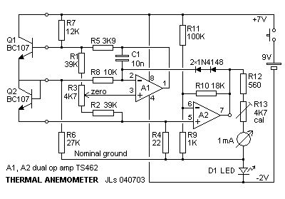 Source: fonema.se
Davis has included a wind direction vane but still refers to the entire instrument as an anemometer. Fig33 Circuit Diagram of Microcontroller Unit. The voltage output from these anemometers is thus the result of some sort of circuit within the device trying to maintain the specific variable current voltage or temperature constant. The anemometer was going to be at the end of about 25m of cable so I used a separate power supply and isolated it from the Arduino board. Speed component of the sensor anemometer The use of this design also allows the anemometer to be used in circuits down to zero voltage and current without reducing the life expectancy of the reed switch.
 Source: shutterstock.com
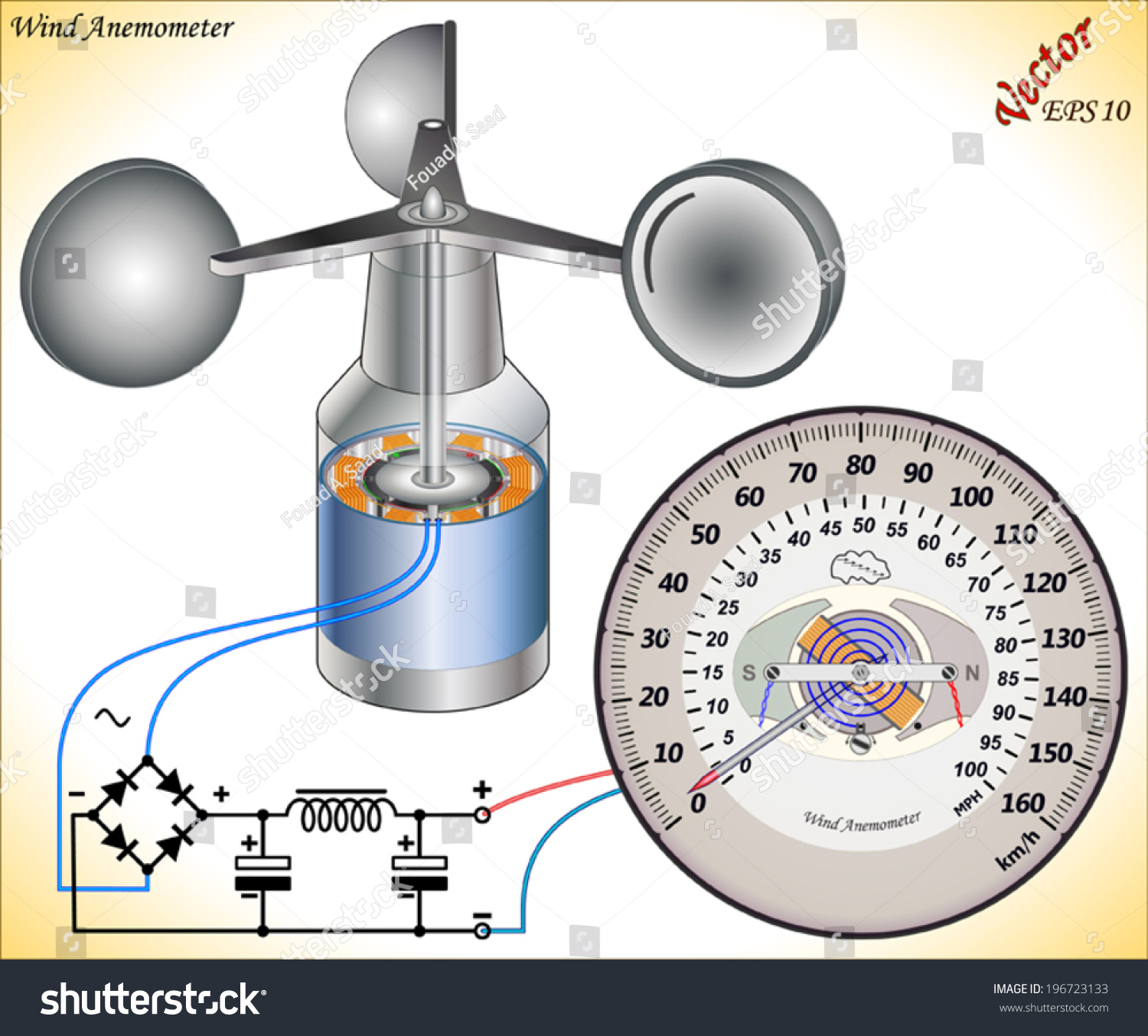
If possible install the anemometer in the center of flat roofs. The main components are. Constant current method Hot wire Anemometer. The anemometer was going to be at the end of about 25m of cable so I used a separate power supply and isolated it from the Arduino board. Find Wind Anemometer Circuit Diagram stock images in HD and millions of other royalty-free stock photos illustrations and vectors in the Shutterstock collection.
 Source: researchgate.net
September 30 2013 By Shivam Chudasama. If possible install the anemometer in the center of flat roofs. Figure 2 shows the circuit diagram for the entire assembly. Davis has included a wind direction vane but still refers to the entire instrument as an anemometer. The anemometer requires a power source between 7V.
This site is an open community for users to share their favorite wallpapers on the internet, all images or pictures in this website are for personal wallpaper use only, it is stricly prohibited to use this wallpaper for commercial purposes, if you are the author and find this image is shared without your permission, please kindly raise a DMCA report to Us.
If you find this site good, please support us by sharing this posts to your own social media accounts like Facebook, Instagram and so on or you can also save this blog page with the title anemometer circuit diagram by using Ctrl + D for devices a laptop with a Windows operating system or Command + D for laptops with an Apple operating system. If you use a smartphone, you can also use the drawer menu of the browser you are using. Whether it’s a Windows, Mac, iOS or Android operating system, you will still be able to bookmark this website.