Atkinson cycle ts diagram
Home » Background » Atkinson cycle ts diagramYour Atkinson cycle ts diagram images are ready in this website. Atkinson cycle ts diagram are a topic that is being searched for and liked by netizens now. You can Find and Download the Atkinson cycle ts diagram files here. Get all free photos.
If you’re searching for atkinson cycle ts diagram pictures information connected with to the atkinson cycle ts diagram keyword, you have come to the right site. Our site always provides you with hints for downloading the maximum quality video and picture content, please kindly search and find more informative video content and graphics that fit your interests.
Atkinson Cycle Ts Diagram. A Carnot cycle using steam as a working substance is represented or p-v and t-s diagram as shown in the figure. The external combustion engine involves the Brayton cycle Rankine cycle Stirling cycle and Ericsson cycle. An ideal air-standard Otto cycle has a compression ratio of 9 and a maximum pressure of 6318 atm. It works on either air or any other gas.
 How Does Atkinson Cycle Work What Is An Atkinson Cycle Engine From mechanicalboost.com
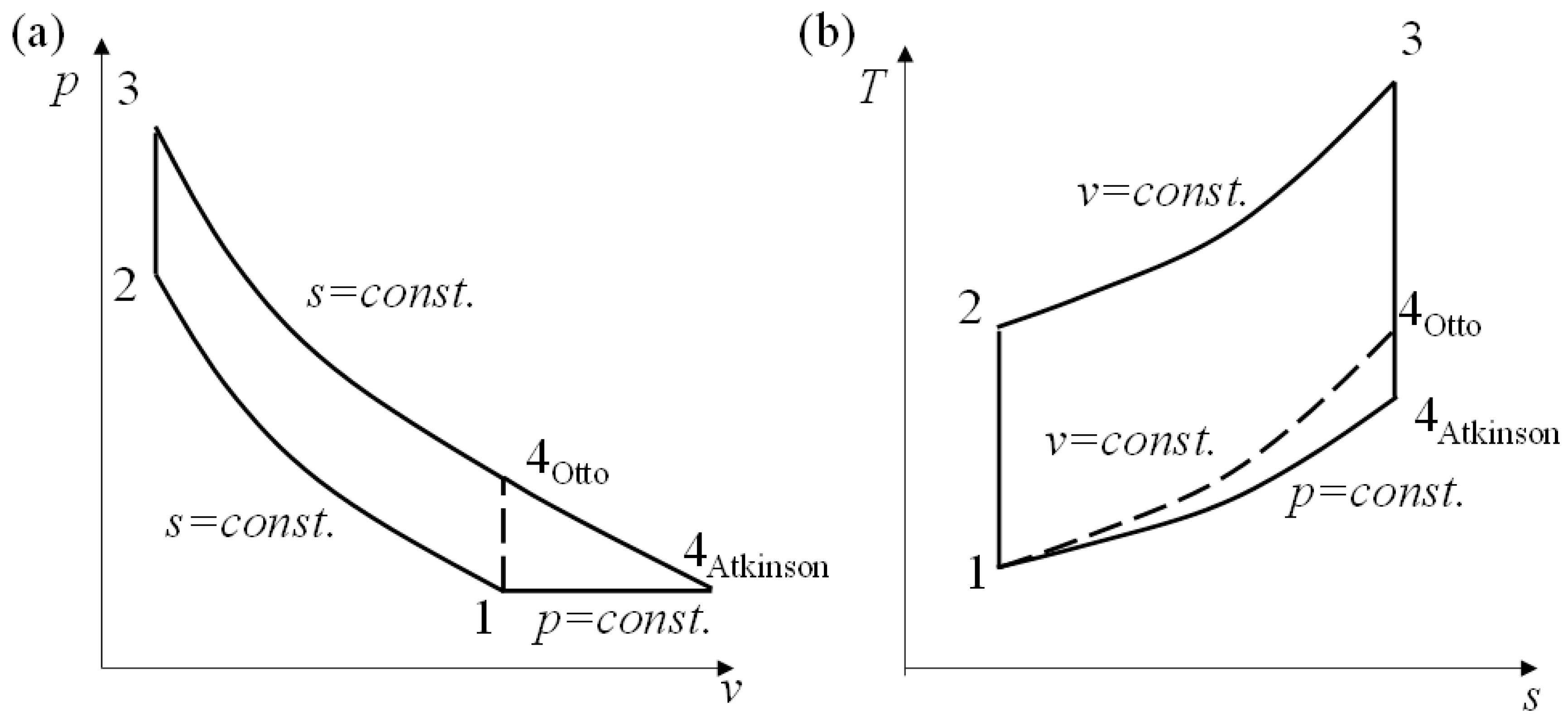
At the beginning of the compression process the cylinder has a mass of 005 kg P11 atm and T1330 K. The compression ratios that maximize the work of the Otto cycle are always found to be higher than those for the Atkinson cycle at the same operating conditions. On the basis of research workers 12 23 e ects of relative air fuel ratio fuel mass ow rate and residual gases on the performance of the air standard Atkinson cycle are derived in this paper. Process4-1 heat rejection at constant pressure. Capacity of Steam Power Plant. PV and TS diagram for Atkinson Cycle.
The cycle comprises the following processes.
Slide 14 of 53. Brayton Cycle Simple Gas Turbine Cycle Vapour Power Cycles. Stirling cycle ts diagram. An Atkinson cycle has a greater work output and a higher thermal efficiency than the Otto cycle at the same operating condition. What is PV TS diagram. The operation of the Atkinson cycle is depicted on a p - V diagram in Fig.
 Source: researchgate.net
Thermodynamic analysis The pressure volume P V and the temperature entropy T S diagrams of an irreversible Atkinson heat. Slide 14 of 53. The Atkinson cycle delays the intake valves closing until the piston has completed 20 to 30 percent of its upward travel on the compression stroke. Figure 4. Otto Cycle pV diagram of Otto Cycle.
 Source: extrudesign.com
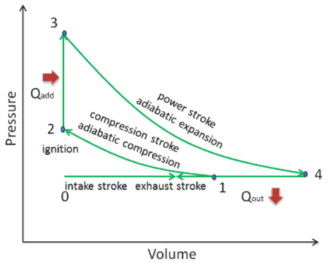
Atkinson Cycle The cycle of the Otto engine is called the Otto cycleIt is the one of most common thermodynamic cycles that can be found in automobile engines and describes the functioning of a typical spark. Otto Cycle is used in all two-stroke and four-stroke petrol engines of motorcycles cars and in other light-duty vehicles. Atkinson Cycle The point 1 represents that the cylinder is full of air with volume V₁ pressure p₁ and absolute temperature T₁. The cycle comprises the following processes. Application of Otto Cycle.
 Source: researchgate.net
What is PV TS diagram. PV diagram for Atkinson Cycle. As a result some of the fresh charge is. While originally seen exclusively in hybrid electric applications such as the earlier-generation Toyota Prius later hybrids and some. Brayton cycle with intercooling reheating and regeneration The net work output of a gas-turbine cycle improves as a result of intercooling and.
 Source: br.pinterest.com
With PV and TS diagram explain about Stirling cycle and derive the equation for thermal efficiency10 14. Otto Cycle pV diagram of Otto Cycle. The PV. A variation of this approach is used in some modern automobile engines. Process4-1 heat rejection at constant pressure.
 Source: researchgate.net
Comparative Study of P-V and T-S diagram of Various Thermodynamic Cycles Like. An Atkinson cycle has a greater work output and a higher thermal efficiency than the Otto cycle at the same operating condition. Answer to Sketch the P-v and T-s diagrams for the Atkinson. This stirling cycle is classified by 4 idealized thermodynamic processes. Process 3-4 is adiabatic expansion process.
 Source: researchgate.net
Answer to Sketch the P-v and T-s diagrams for the Atkinson. The operation of the Atkinson cycle is depicted on a p - V diagram in Fig. An Atkinson cycle has a greater work output and a higher thermal efficiency than the Otto cycle at the same operating condition. The compression ratios that maximize the work of the Otto cycle are always found to be higher than those for the Atkinson cycle at the same operating conditions. T-s diagram of an ideal gas-turbine cycle with intercooling reheating and regeneration.
 Source: researchgate.net
Process 3-4 is adiabatic expansion process. Deviation of Actual Cycle from Ideal Cycle. In an ideal Atkinson cycle the gas is compressed is entropically from 1 bar 27 C to 4 bar. A variation of this approach is used in some modern automobile engines. Process 3-4 is adiabatic expansion process.
 Source: researchgate.net
This cycle is used to model the gas turbines and jet engines. The temperature-entropy diagram Ts diagram in which the thermodynamic state is specified by a point on a graph with specific entropy s as the horizontal axis and absolute temperature T as the vertical axis. Deviation of Actual Cycle from Ideal Cycle. Process2-3 is a heat addition at constant volume. Rankine Cycle Sterling Cycle Atkinson Cycle Ericssion Cycle Bell Coleman Cycle or Reverse Brayton Cycle Brayton Cycle Otto Cycle Ideal Diesel Cycle Dual Cycle Carnot Cycle.
 Source: pinterest.com
Process 3-4 is adiabatic expansion process. The compression ratios that maximize the work of the Otto cycle are always found to be higher than those for the Atkinson cycle at the same operating conditions. Determine a the heat addition kJ b the. As a result some of the fresh charge is. The temperature-entropy diagram Ts diagram in which the thermodynamic state is specified by a point on a graph with specific entropy s as the horizontal axis and absolute temperature T as the vertical axis.
 Source: pinterest.com
Mean Temperature of Heat Addition. At the beginning of the compression process the cylinder has a mass of 005 kg P11 atm and T1330 K. It describes the working of a constant pressure heat engine. Process2-3 is a heat addition at constant volume. Limited Pressure Cycle or Dual Cycle Comparison of Otto Diesel and Dual Cycles.
 Source: thermal-engineering.org
While originally seen exclusively in hybrid electric applications such as the earlier-generation Toyota Prius later hybrids and some. Answer to Sketch the P-v and T-s diagrams for the Atkinson. Atkinson Cycle Processes. This cycle is used to model the gas turbines and jet engines. Atkinson Cycle The point 1 represents that the cylinder is full of air with volume V₁ pressure p₁ and absolute temperature T₁.
 Source: mdpi.com
Process 3-4 is adiabatic expansion process. The temperature-entropy diagram Ts diagram in which the thermodynamic state is specified by a point on a graph with specific entropy s as the horizontal axis and absolute temperature T as the vertical axis. Brayton cycle with intercooling reheating and regeneration The net work output of a gas-turbine cycle improves as a result of intercooling and. Atkinson Cycle Processes. Comparative Study of P-V and T-S diagram of Various Thermodynamic Cycles Like.
 Source: researchgate.net
The external combustion engine involves the Brayton cycle Rankine cycle Stirling cycle and Ericsson cycle. The compression ratios that maximize the work of the Otto cycle are always found to be higher than those for the Atkinson cycle at the same operating conditions. The temperature-entropy diagram Ts diagram in which the thermodynamic state is specified by a point on a graph with specific entropy s as the horizontal axis and absolute temperature T as the vertical axis. With PV and TS diagram explain about Stirling cycle and derive the equation for thermal efficiency10 14. The external combustion engine involves the Brayton cycle Rankine cycle Stirling cycle and Ericsson cycle.
 Source: researchgate.net
In an Atkinson cycle modified Otto cycle the system executing the cycle undergoes a series of four processes. The PV. Answer to Sketch the P-v and T-s diagrams for the Atkinson. T-s diagram of an ideal gas-turbine cycle with intercooling reheating and regeneration. In an ideal Atkinson cycle the gas is compressed is entropically from 1 bar 27 C to 4 bar.
 Source: in.pinterest.com
Atkinson Cycle Fig. An Atkinson cycle has a greater work output and a higher thermal efficiency than the Otto cycle at the same operating condition. Consider 1kg of water at pressure P1 and absolute temperature T1 as represented by. In an Atkinson cycle modified Otto cycle the system executing the cycle undergoes a series of four processes. The PV.
 Source: mdpi.com
This is the information about the Otto Cycle and Otto Cycle T-S diagram and Otto Cycle P-V diagram. Otto Cycle See also. Stirling engine is a. Atkinson Cycle The point 1 represents that the cylinder is full of air with volume V₁ pressure p₁ and absolute temperature T₁. Otto Cycle pV diagram of Otto Cycle.
 Source: mechanicalboost.com
Comparative Study of P-V and T-S diagram of Various Thermodynamic Cycles Like. The Atkinson cycle is designed to provide efficiency at the expense of power density. PV and TS diagram for Atkinson Cycle. For this cycle we have V2. Atkinson Cycle Fig.

The PV. Capacity of Steam Power Plant. Slide 14 of 53. PV diagram for Atkinson Cycle. A Work done per kg of cycle b Thermal efficiency of the cycle.
This site is an open community for users to do sharing their favorite wallpapers on the internet, all images or pictures in this website are for personal wallpaper use only, it is stricly prohibited to use this wallpaper for commercial purposes, if you are the author and find this image is shared without your permission, please kindly raise a DMCA report to Us.
If you find this site helpful, please support us by sharing this posts to your own social media accounts like Facebook, Instagram and so on or you can also bookmark this blog page with the title atkinson cycle ts diagram by using Ctrl + D for devices a laptop with a Windows operating system or Command + D for laptops with an Apple operating system. If you use a smartphone, you can also use the drawer menu of the browser you are using. Whether it’s a Windows, Mac, iOS or Android operating system, you will still be able to bookmark this website.