Band diagram of mosfet
Home » Wallpapers » Band diagram of mosfetYour Band diagram of mosfet images are available. Band diagram of mosfet are a topic that is being searched for and liked by netizens now. You can Get the Band diagram of mosfet files here. Find and Download all free images.
If you’re searching for band diagram of mosfet images information linked to the band diagram of mosfet interest, you have pay a visit to the right blog. Our site frequently provides you with hints for refferencing the maximum quality video and image content, please kindly search and find more informative video content and graphics that fit your interests.
Band Diagram Of Mosfet. AExperimental characteristics of a MOSFET with L 27 µm x0 005 µm. Band diagram of MOSFET - YouTube. As shown in the above figure insulating SiO2 layer has large energy band gap of 8 eV and work function is 095 eV. 2 MOSFETs are barrier controlled devices the drain current is controlled by the height of an energy barrier between the source and channel.
 Draw And Explain Energy Band Diagram Of Mos Capacitor In Accumulation Depletion And Inversion Layer From ques10.com
The band diagram for V g 0 Fig. In solid state physics of semiconductors a band diagram is a diagram plotting various key electron energy levels fermi level and nearby energy band edges as a function of some spatial dimension which is often denoted x. The MOS structure is formed as a sandwich consisting of a semiconductor layer either p or n-type from a single crystal of silicon a layer of silicon dioxide and a layer of metal or n or p polysilicon layer. Effects of velocity saturation on the MOSFET I-V characteristics. SiO 2 Gate P-body V g N N. Notice that inversion occurred when the surface potential is twice the Fermi potential which follows equation 51.
63 The MOS structure The energy band diagram of a MOS structure using a p-type semiconductor is shown in the figure under thermal equilibrium V0.
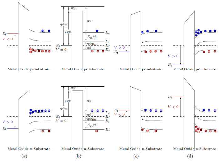
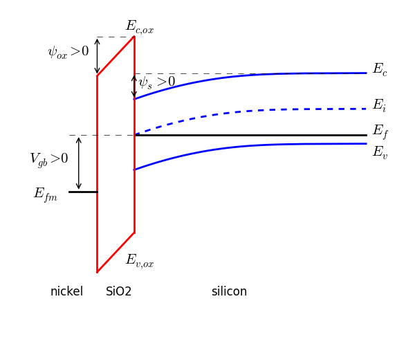
Where E_C conduction band energy level E_F Fermi energy level E_V valance band energy level E_i intrinsic energy level. 3 Depletion and inversion width in a MOS Consider a close up of band structure of the oxide semiconductor interface under bias as shown in gure 4. Thus the MOS is in inversion. Gate and the body on the left- and right-hand sides as shown in Fig. These diagrams help to explain the operation of many kinds of. The energy band diagram contains the electron energy levels in the MOS structure as deliniated with the fermi energy in the metal and semiconductor as well as the conduction and valence band edge in the oxide and the silicon.
 Source: favpng.com
In this module on MOS devices we will cover the following topics MOS device structure energy band diagram for MOS device at equilibrium Flat band condition Accumulation Depletion and Inversion of MOS under bias Energy band diagram and charge distribution for MOS in inversion Quantitative model and relevant parameters Energy band diagram with channel bias Inversion. 2018 3 In a well-designed transistor the height of the energy. FIGURE 52 An MOS transistor is an MOS capacitor with PN junctions at two ends. The energy band diagram contains the electron energy levels in the MOS structure as deliniated with the fermi energy in the metal and semiconductor as well as the conduction and valence band edge in the oxide and the silicon. The figure given below shows the combined energy band diagram of MOS system.
 Source: researchgate.net
Before discussing the energy diagram the following functions and energies are introduced. MOS Band-Diagram Guidelines cont The barrier height for conduction-band electron flow from the Si into SiO 2 is 31 eV This is equal to the electron-affinity difference χ Si and χ SiO2 The barrier height for valence-band hole flow from the Si into SiO 2 is 48 eV The vertical distance between the Fermi level in the metal E. The energy band diagram contains the electron energy levels in the MOS structure as deliniated with the fermi energy in the metal and semiconductor as well as the conduction and valence band edge in the oxide and the silicon. SiO 2 Gate P-body V g N N. Figure 31a shows a typical structure of a MOS capacitor.
 Source: researchgate.net
FIGURE 53a Polysilicon-gateoxidesemiconductor capacitor and b its energy band diagram with no applied voltage. The energy band diagram for ideal MOS capacitor at thermal equilibrium with zero biased voltage condition is. QΦS inv 2qφF 51 Figure 52. Thus the MOS is in inversion. 2018 3 In a well-designed transistor the height of the energy.
 Source: researchgate.net
In this case applied voltage V_g is less than flat band voltage. Band diagram of MOSFET - YouTube. When the semiconductor in a MOS is in inversion the intrinsic energy level crosses over Fermi level and goes as deep into the other side of Fermi at the interface as distant it is from the Fermi level in the bulk. FIGURE 52 An MOS transistor is an MOS capacitor with PN junctions at two ends. Mosfet Energy Band Diagram Explanation.
 Source: researchgate.net
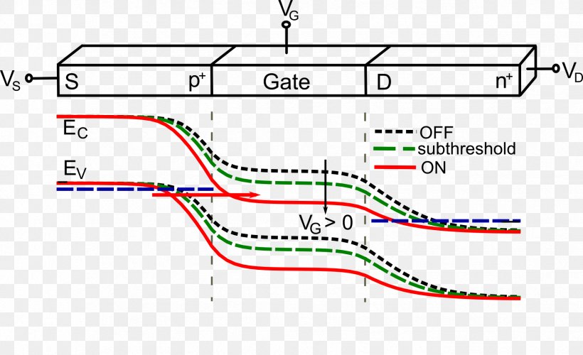
2D energy band diagram on n-MOSFET Lundstrom ECE 305 F16 a b c d SM. Are indicated in Figure 13 where we show typical band diagrams of a MOS capacitor at zero bias and with the voltage V V FB applied to the metal contact relative to the semiconductoroxide interface. Energy band diagram of an ideal MOS structure for V0 flat band condition. Before discussing the energy diagram the following functions and energies are introduced. The energy band diagram for ideal MOS capacitor at thermal equilibrium with zero biased voltage condition is.
 Source: researchgate.net
Metal gate has work function of 41eV. Effects of velocity saturation on the MOSFET I-V characteristics. 53b is quite complex. Energy band diagram of an ideal MOS structure for V0 flat band condition. A device b equilibrium flat band c equilibrium ψ S 0 d non-equilibrium with V G and V D 0 applied F N 22.
 Source: researchgate.net
2D energy band diagram on n-MOSFET Lundstrom ECE 305 F16 a b c d SM. The energy band diagram contains the electron energy levels in the MOS structure as deliniated with the fermi energy in the metal and semiconductor as well as the conduction and valence band edge in the oxide and the silicon. Thus the MOS is in inversion. The energy band diagram for ideal MOS capacitor at thermal equilibrium with zero biased voltage condition is. 2018 3 In a well-designed transistor the height of the energy.

In solid state physics of semiconductors a band diagram is a diagram plotting various key electron energy levels fermi level and nearby energy band edges as a function of some spatial dimension which is often denoted x. The work function qΦ is defined. Gate and the body on the left- and right-hand sides as shown in Fig. Before discussing the energy diagram the following functions and energies are introduced. Based on the band diagram it is possible to de ne a few potential terms 1.
 Source: researchgate.net
Here the intrinsic Femi level is below E FS by ϕ B in the bulk and above E FS by ϕ B at the interface. In this case applied voltage V_g is less than flat band voltage. S - surface potential. MOS Band-Diagram Guidelines cont The barrier height for conduction-band electron flow from the Si into SiO 2 is 31 eV This is equal to the electron-affinity difference χ Si and χ SiO2 The barrier height for valence-band hole flow from the Si into SiO 2 is 48 eV The vertical distance between the Fermi level in the metal E. Here the work functions are different so it will create voltage drop across the MOS system.
 Source: youtube.com
Before discussing the energy diagram the following functions and energies are introduced. These diagrams help to explain the operation of many kinds of. MOS Transistor 9 ec 5 104 Vcm for holes hence velocity saturation for P-channel MOSFET will not become important until L 025 µm. AExperimental characteristics of a MOSFET with L 27 µm x0 005 µm. Based on the band diagram it is possible to de ne a few potential terms 1.
 Source: researchgate.net
Sze Physics of Semiconductor Devices 1981 and Pao and Sah. Energy band diagram of the combined MOS system Flat Band VoltageIt is the voltage corresponding to the potential difference applied externally between the gate and the substrate so that the bending of the energy bands near the surface can be compensated ie the energy bands become flat. 53b is quite complex. Figure 31a shows a typical structure of a MOS capacitor. The energy band diagram for ideal MOS capacitor at thermal equilibrium with zero biased voltage condition is.
 Source: researchgate.net
The energy band diagram of p-type MOS device at inversion condition. Metal gate has work function of 41eV. S E Fi surface E Fi bulk. 2 MOSFETs are barrier controlled devices the drain current is controlled by the height of an energy barrier between the source and channel. QΦS inv 2qφF 51 Figure 52.
 Source: ques10.com
B - bulk potential. 3 Depletion and inversion width in a MOS Consider a close up of band structure of the oxide semiconductor interface under bias as shown in gure 4. Here the intrinsic Femi level is below E FS by ϕ B in the bulk and above E FS by ϕ B at the interface. Where E_C conduction band energy level E_F Fermi energy level E_V valance band energy level E_i intrinsic energy level. Metal gate has work function of 41eV.
 Source: shefalitayal.com
MOS Band-Diagram Guidelines cont The barrier height for conduction-band electron flow from the Si into SiO 2 is 31 eV This is equal to the electron-affinity difference χ Si and χ SiO2 The barrier height for valence-band hole flow from the Si into SiO 2 is 48 eV The vertical distance between the Fermi level in the metal E. The work function qΦ is defined. 2D energy band diagram on n-MOSFET Lundstrom ECE 305 F16 a b c d SM. AExperimental characteristics of a MOSFET with L 27 µm x0 005 µm. Here the intrinsic Femi level is below E FS by ϕ B in the bulk and above E FS by ϕ B at the interface.
 Source: youtube.com
S - surface potential. The work function qΦ is defined. Energy band diagram of an ideal MOS structure for V0 flat band condition. The energy band diagram of p-type MOS device at inversion condition. FIGURE 53a Polysilicon-gateoxidesemiconductor capacitor and b its energy band diagram with no applied voltage.
 Source: iue.tuwien.ac.at
Metal gate has work function of 41eV. QΦS inv 2qφF 51 Figure 52. 53b is quite complex. The metaloxidesemiconductor field-effect transistor MOSFET MOS-FET or MOS FET also known as the metaloxidesilicon transistor MOS transistor or MOS is a type of insulated-gate field-effect transistor that is fabricated by the controlled oxidation of a semiconductor typically siliconThe voltage of the covered gate determines the electrical conductivity of the device. In this module on MOS devices we will cover the following topics MOS device structure energy band diagram for MOS device at equilibrium Flat band condition Accumulation Depletion and Inversion of MOS under bias Energy band diagram and charge distribution for MOS in inversion Quantitative model and relevant parameters Energy band diagram with channel bias Inversion.
 Source: researchgate.net
62 Energy band diagram of an MOS capacitor. This coures covers the Metal-Semiconductor Contact Metal-Oxide-Semiconductor MOS capapcitor Metal-Oxide-Semiconductor Field Effect Transistors MOSFETs CMOS Metal-Semiconductor Field Effect Transistors MESFETs Memory and Bipolar Junction Transistor BJT to improve the overall knowledge of semiconductor industry. The energy band diagram for ideal MOS capacitor at thermal equilibrium with zero biased voltage condition is. Sze Physics of Semiconductor Devices 1981 and Pao and Sah. Fig1 energy band diagram and MOSFET internal charge distribution in accumulation region.
 Source: h-gens.github.io
Gate and the body on the left- and right-hand sides as shown in Fig. In solid state physics of semiconductors a band diagram is a diagram plotting various key electron energy levels fermi level and nearby energy band edges as a function of some spatial dimension which is often denoted x. The work function qΦ is defined. As shown in the above figure insulating SiO2 layer has large energy band gap of 8 eV and work function is 095 eV. Voltage applied to gateon metal side is negative.
This site is an open community for users to share their favorite wallpapers on the internet, all images or pictures in this website are for personal wallpaper use only, it is stricly prohibited to use this wallpaper for commercial purposes, if you are the author and find this image is shared without your permission, please kindly raise a DMCA report to Us.
If you find this site helpful, please support us by sharing this posts to your own social media accounts like Facebook, Instagram and so on or you can also bookmark this blog page with the title band diagram of mosfet by using Ctrl + D for devices a laptop with a Windows operating system or Command + D for laptops with an Apple operating system. If you use a smartphone, you can also use the drawer menu of the browser you are using. Whether it’s a Windows, Mac, iOS or Android operating system, you will still be able to bookmark this website.