Bilge and ballast system diagram
Home » Wallpapers » Bilge and ballast system diagramYour Bilge and ballast system diagram images are ready. Bilge and ballast system diagram are a topic that is being searched for and liked by netizens now. You can Download the Bilge and ballast system diagram files here. Get all royalty-free vectors.
If you’re searching for bilge and ballast system diagram images information related to the bilge and ballast system diagram topic, you have pay a visit to the ideal site. Our website always provides you with suggestions for seeing the highest quality video and image content, please kindly hunt and locate more informative video articles and images that fit your interests.
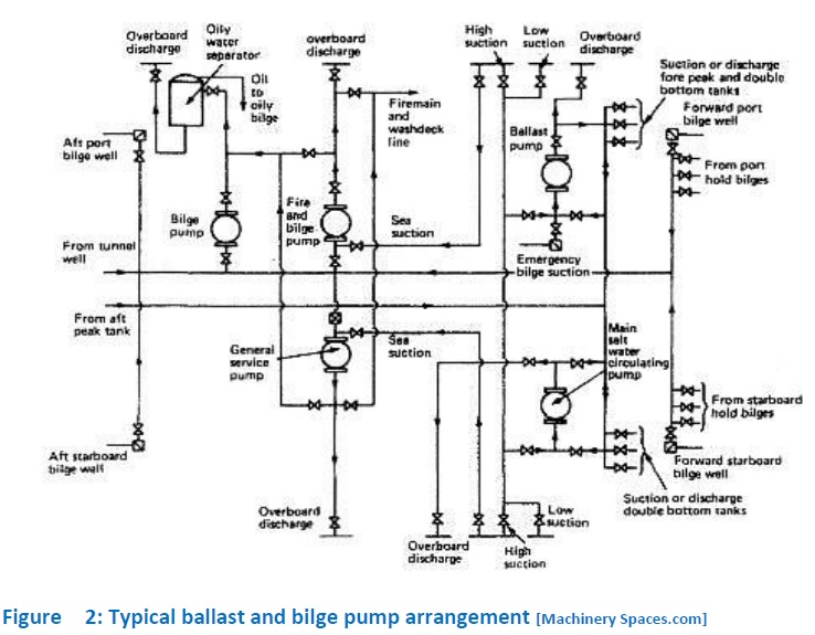
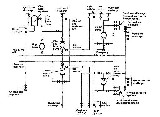
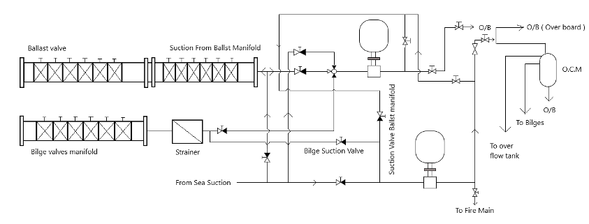
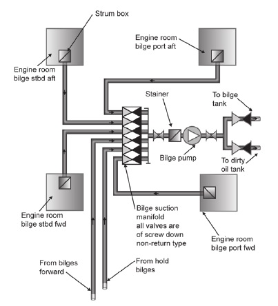
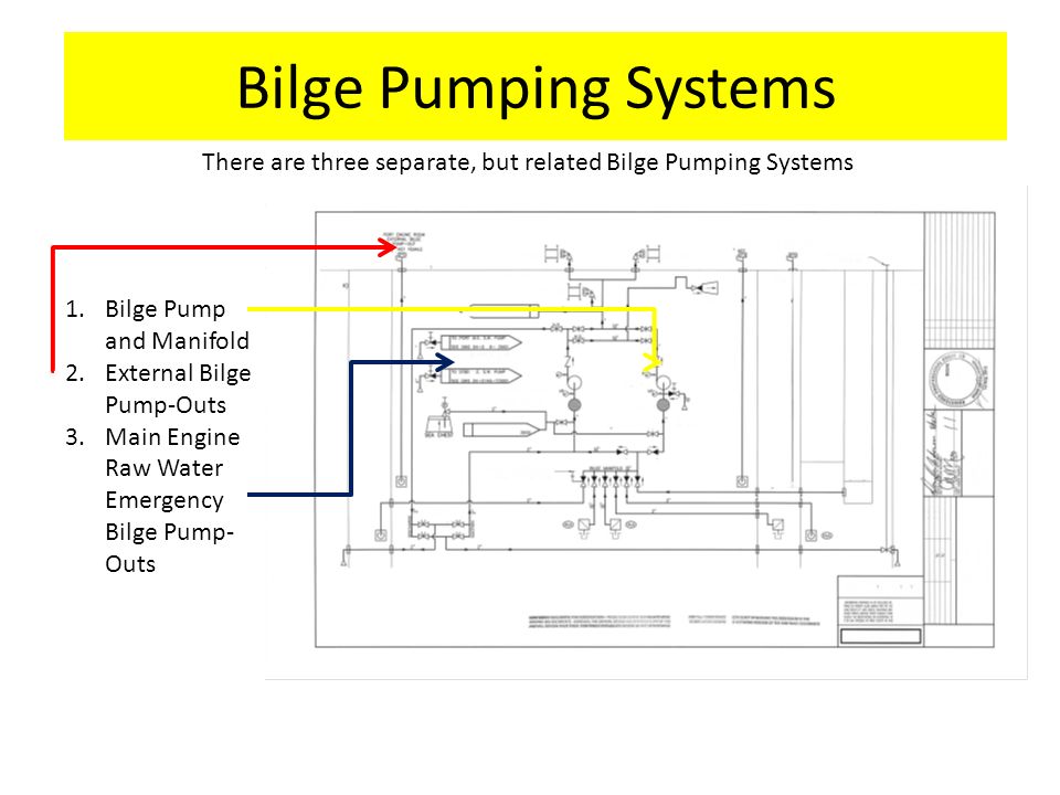
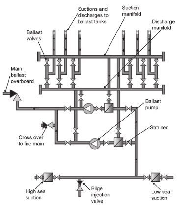
Bilge And Ballast System Diagram. The essential safety role of the bilge system means that bilge pumps must be capable of discharging directly overboard Bilge and Ballast Piping when clearing the water and oil which accumulates in the machinery space bilges the discharge overboard must be via the oilwater separator and usually with the use of the special bilge pump maximum oil concentration of oil. Sketches And Diagrams Of Bilge And Ballast Systems For Marine Machinery Spaces. Bilge and ballast piping may be of cast or wrought iron steel copper or other approved materials. - Bila dijadikan satu dengan Firemain System maka dapat digunakan untuk memadamkan api saat terjadi kebakaran.
 Diagram Lithonia T8 Lighting Wiring Diagram 110 277 Full Version Hd Quality 110 277 Mediagrame Prcsestosg It From mediagrame.prcsestosg.it
Ballast Water Management Bwm And Energy Efficiency. Sketches and Diagrams of Bilge and Ballast Systems for Marine Machinery Spaces. - Bila instalasi diberikan sambungan ke arah main deck maka air dari Sea Chest dapat digunakan untuk cuci geladak. Sistem ini memiliki fungsi utama yaitu sebagai penguras drainage apabila tejadi kebocoran pada kapal yang disebabkan oleh grounding kandas atau Collision sistem harus mampu memindahkan air dengan cepat dari bagian. Location Ballast tanks are located between deck and hull out-of-sight. The bilge pump is primed by an integral centrifugal displacement type priming pump.
When the vessel is first launched set ballast pump switches to drain.
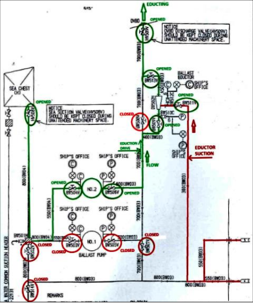
The ballast system is used as a stabilization device. Piping Diagram BWMS integrated with existing BWS BWMS Operation Manual Ballast Water Management Plan D1D1D2D2 Type Approval Certificate TAC Hazard Analysis If Applicable Commissioning Procedure Bilge Ventilation piping diagram Piping Diagram Fresh Water Compressed Air System As Applicable Updated General Arrangement 3D Model. - Bila instalasi diberikan sambungan ke arah main deck maka air dari Sea Chest dapat digunakan untuk cuci geladak. 117 Sectional area of sounding pipes. Ballast System For safe operation at least two ballast pumps are to be connected to ballast tanks Stripping eductor can also be used for emptying the bilges in cargo holds with 2 non-return valves between hold and system Ship side valve material must not of grey cast iron and to direct mechanical. Following Schematic Diagrams will assist in understanding the general arrangement of tanks on board the location 01 sounding ports manholes the ballast pipe line system and the line diagram in the Engine Room.
 Source: shipsbusiness.com
- Bila instalasi diberikan sambungan ke arah main deck maka air dari Sea Chest dapat digunakan untuk cuci geladak. Auxiliary Systems Diagram Bilge Ballast Oily Waste 65411-529-01 Rev E Ballast Fire Bilge pump flow curve AMPCO Z Series 3 x 2 10 Hyde Guardian Ballast Water Treatment System Hyde Marine Installation and Operating Manual. G s Control unit I i s The current that is converted from the desired angle is 00 current. Piping Diagram BWMS integrated with existing BWS BWMS Operation Manual Ballast Water Management Plan D1D1D2D2 Type Approval Certificate TAC Hazard Analysis If Applicable Commissioning Procedure Bilge Ventilation piping diagram Piping Diagram Fresh Water Compressed Air System As Applicable Updated General Arrangement 3D Model. When unloading the water is put in tanks on the opposite side that the boom is swung out at to counteract the list.
 Source: safety4sea.com
117 Sectional area of sounding pipes. On the XStar front ballast. Bilge and ballast piping may be of cast or wrought iron steel copper or other approved materials. Combined or separate mains for suction and discharge may be provided. Auxiliary Systems Diagram Bilge Ballast Oily Waste 65411-529-01 Rev E Ballast Fire Bilge pump flow curve AMPCO Z Series 3 x 2 10 Hyde Guardian Ballast Water Treatment System Hyde Marine Installation and Operating Manual.
 Source: machineryspaces.com
Auxiliary Systems Diagram Bilge Ballast Oily Waste 65411-529-01 Rev E Ballast Fire Bilge pump flow curve AMPCO Z Series 3 x 2 10 Hyde Guardian Ballast Water Treatment System Hyde Marine Installation and Operating Manual. - Bilge and Ballast Piping Diagram - Wiring Diagram - Steering Gear Systems Piping and Arrangements and Steering Gear Manufacturer make and model information - Torsional vibration calculations for vessels less than two 2 years old torsional. If possible the bilge pipes are kept out of the double bottom tanks and in way of a deep tank are led through a pipe tunnel. Combined or separate mains for suction and discharge may be provided. For simple outings and quicker reaction by the boat ballast systems can be left empty.
 Source: marineinsight.com
Sketches And Diagrams Of Bilge And Ballast Systems For Marine Machinery Spaces. Location Ballast tanks are located between deck and hull out-of-sight. Bilge and ballast piping diagram. 18 Bilge and ballast The arrangement of the bilge and ballast pumping system shall be such as to prevent the possibility of water passing from the sea and from water ballast spaces into the cargo and machinery spaces or from one compartment to another. 1171 The internal diameter of sounding pipes shall not be less than 32 mm.
 Source: shipfever.com
Combined or separate mains for suction and discharge may be provided. The aerator pump system is the first and still most common ballast system. G s Control unit I i s The current that is converted from the desired angle is 00 current. The bilge pump is primed by an integral centrifugal displacement type priming pump. The essential safety role of the bilge system means that bilge pumps must be capable of discharging directly overboard Bilge and Ballast Piping when clearing the water and oil which accumulates in the machinery space bilges the discharge overboard must be via the oilwater separator and usually with the use of the special bilge pump maximum oil concentration of oil.
 Source: mmercourt.medievalarte.it
When the boat isnt carrying any cargo ballast water is used to weigh down the boat so it isnt getting thrown all over the place by rough seas or the wind. Ballast SystemBallast System 9. The emergency bilge suction or bilge injection valve is used to prevent flooding of the ship. Mengenai Firemain System akan dibahas pada kesempatan berikutnya. If the peaks are used as tanks then a power pump suction is led to each peak.
 Source: machineryspaces.com
Cross Section Of Ships Showing Ballast Tanks And Ballast Water Cycle Download Scientific Diagram. Auxiliary Systems Diagram Bilge Ballast Oily Waste 65411-529-01 Rev E Ballast Fire Bilge pump flow curve AMPCO Z Series 3 x 2 10 Hyde Guardian Ballast Water Treatment System Hyde Marine Installation and Operating Manual. When the vessel is first launched set ballast pump switches to drain. If the peaks are used as tanks then a power pump suction is led to each peak. The piping is fitted in lengths which are adequately supported and have flanged connections provision being made for expansion in each range of pipes.
 Source: mediagrame.prcsestosg.it
Following Schematic Diagrams will assist in understanding the general arrangement of tanks on board the location 01 sounding ports manholes the ballast pipe line system and the line diagram in the Engine Room. Lead or other heat sensitive materials are not permitted. Bilge and ballast piping diagram. Wakeboard Ballast System Design. If the peaks are used as tanks then a power pump suction is led to each peak.
 Source: takis.medievalarte.it
See Vessel Plans for locations. If the peaks are used as tanks then a power pump suction is led to each peak. Where a tank or cargo space can be used for ballast or dry cargo then either a ballast or bilge connection will be required. Location Ballast tanks are located between deck and hull out-of-sight. The essential safety role of the bilge system means that bilge pumps must be capable of discharging directly overboard Bilge and Ballast Piping when clearing the water and oil which accumulates in the machinery space bilges the discharge overboard must be via the oilwater separator and usually with the use of the special bilge pump maximum oil concentration of oil.
 Source: slideplayer.com
Cross Section Of Ships Showing Ballast Tanks And Ballast Water Cycle Download Scientific Diagram. Tank Pipe Fitting And Pipeline Security System For A Ship Bright Hub Engineering. For heavy fuel oil tanks the internal diameter shall not be less than 50 mm. Instalasi Pipa Bilge Ballast berguna untuk. Often a separate dirty ballast system is arranged to overcome this problem.
 Source: semanticscholar.org
On the XStar front ballast. Steel 100 Ft Design 3006 Flight One FSN 1925-375-3003 Manual. Ballast System For safe operation at least two ballast pumps are to be connected to ballast tanks Stripping eductor can also be used for emptying the bilges in cargo holds with 2 non-return valves between hold and system Ship side valve material must not of grey cast iron and to direct mechanical. See Vessel Plans for locations. Plugin optional bags are located in the rear storage areas on either side of the engine compartment.

The aerator pump system is the first and still most common ballast system. Auxiliary Systems Diagram Bilge Ballast Oily Waste 65411-529-01 Rev E Ballast Fire Bilge pump flow curve AMPCO Z Series 3 x 2 10 Hyde Guardian Ballast Water Treatment System Hyde Marine Installation and Operating Manual. This will re-set the system to zero. Wakeboard ballast is defined as the storage of mass within a boat to displace the hull deeper in the water which in turn changes both the wake size and shape. DRAIN to empty the tanks set switches to drain un-til desired wake is set andor the tanks are empty when.
 Source: maime.lampadineantizanzare.it
This will re-set the system to zero. If possible the bilge pipes are kept out of the double bottom tanks and in way of a deep tank are led through a pipe tunnel. This will re-set the system to zero. The piping is fitted in lengths which are adequately supported and have flanged connections provision being made for expansion in each range of pipes. Often a separate dirty ballast system is arranged to overcome this problem.
 Source: marineinsight.com
Steel 100 Ft Design 3006 Flight One FSN 1925-375-3003 Manual. These are schematic or block diagrams and not to scale. Block Diagram of Ballast Control System Where. In the case of remote sounding based on the air-bubble principle two air bubble lines per tank may be accepted. The emergency bilge suction or bilge injection valve is used to prevent flooding of the ship.
 Source: youtube.com
Ballast Water Management Bwm And Energy Efficiency. Sistem Bilga Bilge System Didalam kapal sistem ini merupakan salah satu sistem yang digunakan untuk keselamatan kapal. For heavy fuel oil tanks the internal diameter shall not be less than 50 mm. See Vessel Plans for locations. The ballast system is used as a stabilization device.
 Source: machineryspaces.com
If the peaks are used as tanks then a power pump suction is led to each peak. Sketches And Diagrams Of Bilge And Ballast Systems For Marine Machinery Spaces. The aerator pump system is the first and still most common ballast system. The bilge and ballast pump is a vertical single stage centrifugal double suction direct motor driven unit with a capacity of 600 gpm at 60 feet total head. Tank Pipe Fitting And Pipeline Security System For A Ship Bright Hub Engineering.
 Source: researchgate.net
Where a tank or cargo space can be used for ballast or dry cargo then either a ballast or bilge connection will be required. When the vessel is first launched set ballast pump switches to drain. DRAIN to empty the tanks set switches to drain un-til desired wake is set andor the tanks are empty when. This will re-set the system to zero. The aerator pump system is the first and still most common ballast system.
 Source: mediagrame.prcsestosg.it
Location Ballast tanks are located between deck and hull out-of-sight. This will re-set the system to zero. Lead or other heat sensitive materials are not permitted. If the peaks are used as tanks then a power pump suction is led to each peak. Sketches And Diagrams Of Bilge And Ballast Systems For Marine Machinery Spaces Ballast Water Management Bwm And Energy Efficiency Cross Section Of Ships Showing Ballast Tanks And Ballast Water Cycle Download Scientific Diagram.
This site is an open community for users to submit their favorite wallpapers on the internet, all images or pictures in this website are for personal wallpaper use only, it is stricly prohibited to use this wallpaper for commercial purposes, if you are the author and find this image is shared without your permission, please kindly raise a DMCA report to Us.
If you find this site adventageous, please support us by sharing this posts to your own social media accounts like Facebook, Instagram and so on or you can also bookmark this blog page with the title bilge and ballast system diagram by using Ctrl + D for devices a laptop with a Windows operating system or Command + D for laptops with an Apple operating system. If you use a smartphone, you can also use the drawer menu of the browser you are using. Whether it’s a Windows, Mac, iOS or Android operating system, you will still be able to bookmark this website.