Block diagram algebra solver
Home » Background » Block diagram algebra solverYour Block diagram algebra solver images are available in this site. Block diagram algebra solver are a topic that is being searched for and liked by netizens today. You can Find and Download the Block diagram algebra solver files here. Find and Download all free vectors.
If you’re searching for block diagram algebra solver images information linked to the block diagram algebra solver topic, you have visit the right site. Our website always gives you hints for viewing the highest quality video and image content, please kindly hunt and locate more informative video content and images that match your interests.
Block Diagram Algebra Solver. Series connection is also called cascade connection. Block diagram reduction examples. Use Rule 4 for shifting. Block diagram rules.
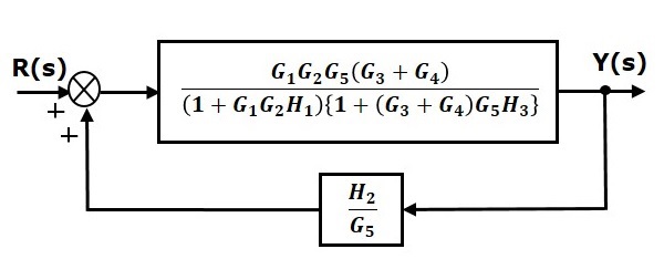 Control Systems Block Diagram Reduction From tutorialspoint.com
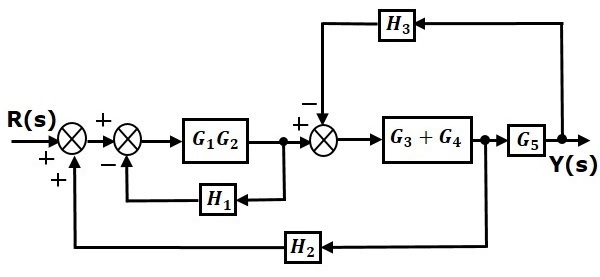
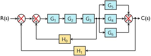
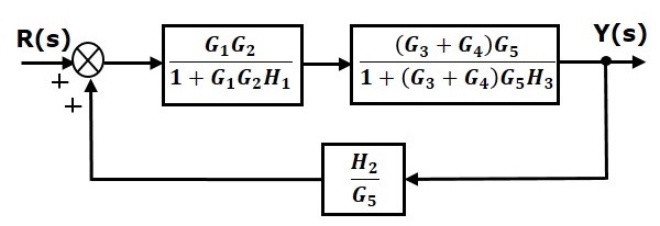
Block diagram algebra is introduced in section 23 as a suitable tool for obtaining transfer functions of systems whose block diagrams are known. System Algebra and Block Diagram. Consider the block diagram shown in the following figure. Moreover the behavior of complex systems composed of a set of interconnected LTI systems can also be easily analyzed in z-domain. This algebra mainly deals with the pictorial representation of algebraic equations. Combine all cascade blocks 2.
Look at the p2 block in the upper left and the multiplication junction to the right of it.
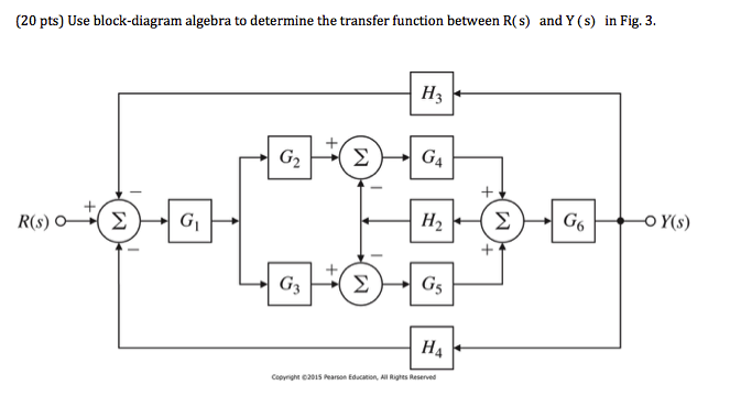
A block diagram showing calculator. You have signals coming into the junction from below and from the right so the line connecting the junction to the p2 block must be an output from the junction to the block. Use Rule 2 for blocks G_3 and G_4. An It can be replaced with. Block Diagram Reduction W3 4Masons Rule and the Signal-Flow Graph A compact alternative notation to the block diagram is given by the signal-ow graph introduced Signal-ow by S. A diagram is shown below.
 Source: tutorialspoint.com
In the current practice of simplify-. System Algebra and Block Diagram. Procedure to solve Block Diagram Reduction Problems. There are a number of rules regarding the simplification of system block diagrams they are listed below. Basic Connections for Blocks.

By solving dPsds 0. Try to shift take off points towards right and Summing point towards left. With transfer function G4s is moved at the right of G4s. By solving dPsds 0. Step 1 Use Rule 1 for blocks G_1 and G_2.
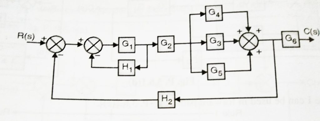 Source: electronicsguide4u.com
Eliminate loop I simplify as GGG B 1G 2HsY 4G 2G 1H AB 3G. Form equivalent cascaded system in the forward path and equivalent. Basic Connections for Blocks. Use Rule 2 for blocks G_3 and G_4. There are three basic types of connections between two blocks.
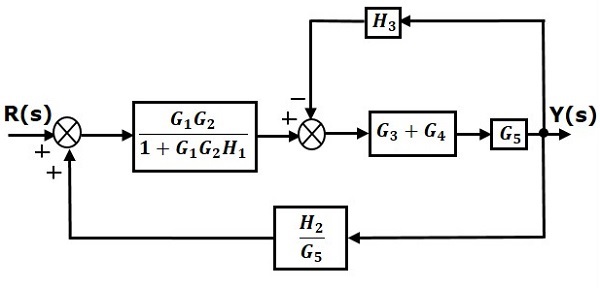 Source: tutorialspoint.com
In the following figure two. Shift summing points to left 5. In the current practice of simplify-. Reduce the minor feedback loops. A1A2A n X Y This is a single block that contains the product of the terms A1 thru An.
 Source: chegg.com
Use Rule 2 for blocks G_3 and G_4. BLOCK DIAGRAM ALGEBRA AND TRANSFER FUNCTIONS OF SYSTEMS 161—t o2o0 Step 3-t -R GIG4 1 – GIG4H1 Step 4. EXAMPLE PROBLEMS AND SOLUTIONS A-3-1. Each step refers to specific transformations listed in Fig. Blocks cascaded in series can be combined in to a single block by multiplying the contents of each block.
 Source: youtube.com
There are a number of rules regarding the simplification of system block diagrams they are listed below. Consider the block diagram shown in the following figure. Shift takeoff points to the right 6. Combine all cascade blocks 2. There are a number of rules regarding the simplification of system block diagrams they are listed below.
 Source: electronicscoach.com
Block diagrams are widely used by engineers for controls signal processing communications and mechatronics. Procedure to solve Block Diagram Reduction Problems. 26 The Routh array starts off as. System Algebra and Block Diagram. Figure 210 Steps in solving Example 51.

It can be shown that an auxiliary polynomial of degree 2n has n pairs of roots of equal magnitude and opposite sign. Basic Connections for Blocks. 26 The Routh array starts off as. Note that the auxiliary polynomial always has even degree. A block diagram showing calculator.
 Source: erforum.net
Block diagram rules.
 Source: msubbu.in
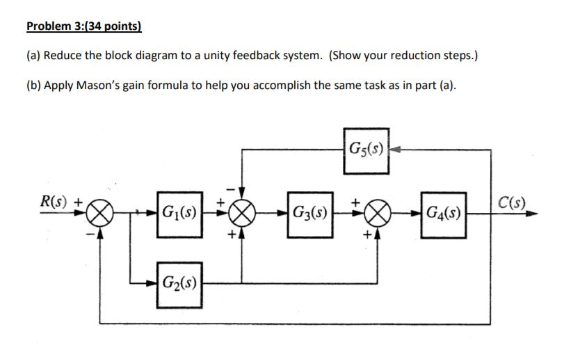
Block Diagram Simplification Example 1 Rearrange the following into a unity -feedback system Move the feedback block 𝐻𝐻𝑠𝑠 forward past the summing junction Add an inverse block on 𝑅𝑅𝑠𝑠to compensate for the move Closed-loop transfer function. Step 2 Use Rule 3 for blocks G_1G_2 and H_1. Consider the block diagram shown in the following figure. First move the branch point of the path involving HI outside the loop involving H as shown in Figure 3-43aThen eliminating two loops results in Figure 3-43bCombining two. An occasional requirement of block diagram reduction is the isolation of a particular block in a feedback or feedforward loop.

Use block diagram manipulation instead of algebra. Some simple interconnections of LTI systems are listed below. An It can be replaced with. Note that the auxiliary polynomial always has even degree. Block diagram algebra is introduced in section 23 as a suitable tool for obtaining transfer functions of systems whose block diagrams are known.
 Source: tutorialspoint.com
The equivalent block diagram is. U 1 u 2 etc to output y use superposition. By solving dPsds 0. A block diagram showing calculator. With transfer function G4s is moved at the right of G4s.
 Source: tutorialspoint.com
Block diagram algebra is nothing but the algebra involved with the basic elements of the block diagram. Eliminate all minor interior feedback loops 4. The final equation is θ sb s d sa s θr sθ s which you can solve for both of the requested transfer functions. Also it can be used together with transfer functions to represent the cause and effect relationships throughout the system. Reduce the blocks connected in parallel Step 3.
 Source: tutorialspoint.com
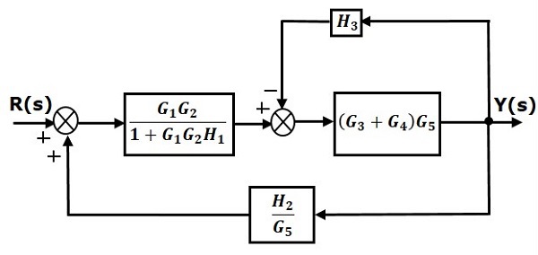
By solving dPsds 0. Z-transform converts time-domain operations such as difference and convolution into algebraic operations in z-domain. Step 2 Use Rule 3 for blocks G_1G_2 and H_1. Simplify the block diagram shown in Figure 3-42. Let us simplify reduce this block diagram using the block diagram reduction rules.
 Source: youtube.com
By solving dPsds 0. Figure 210 Steps in solving Example 51. Block diagrams are widely used by engineers for controls signal processing communications and mechatronics. Webb MAE 4421 11 Block Diagram Algebra Often want to simplify block diagrams into simpler recognizable forms To determine the equivalent transfer function Simplify to instances of the three standard forms then simplify those forms Move blocks around relative to summing junctions and pickoff points simplify to a standard form. System algebra and block diagram.
 Source: web.itu.edu.tr
Basic Connections for Blocks. Block diagram algebra is defined as the algebra involved with the basic elements of the block diagram. Step 2 Use Rule 3 for blocks G_1G_2 and H_1. Reduce the minor feedback loops. Consider the block diagram shown in the following figure.
 Source: chegg.com
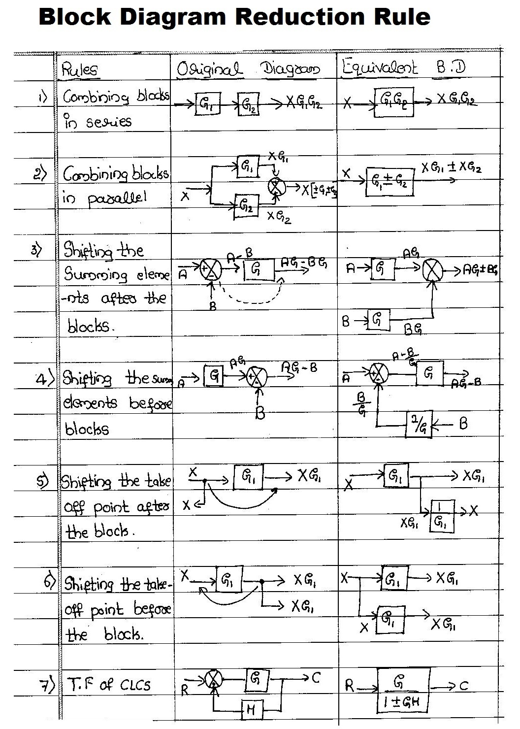
There are a number of rules regarding the simplification of system block diagrams they are listed below. BLOCK DIAGRAM ALGEBRA AND TRANSFER FUNCTIONS OF SYSTEMS 161—t o2o0 Step 3-t -R GIG4 1 – GIG4H1 Step 4. Block diagram algebra for pickoff points equivalent forms for moving a block a. Moreover the behavior of complex systems composed of a set of interconnected LTI systems can also be easily analyzed in z-domain. To the left past a pickoff point.

In the current practice of simplify-. Basic Connections for Blocks. A block diagram showing calculator. Block Diagram Simplification Example 1 Rearrange the following into a unity -feedback system Move the feedback block 𝐻𝐻𝑠𝑠 forward past the summing junction Add an inverse block on 𝑅𝑅𝑠𝑠to compensate for the move Closed-loop transfer function. Combine all cascade blocks 2.
This site is an open community for users to do submittion their favorite wallpapers on the internet, all images or pictures in this website are for personal wallpaper use only, it is stricly prohibited to use this wallpaper for commercial purposes, if you are the author and find this image is shared without your permission, please kindly raise a DMCA report to Us.
If you find this site convienient, please support us by sharing this posts to your favorite social media accounts like Facebook, Instagram and so on or you can also save this blog page with the title block diagram algebra solver by using Ctrl + D for devices a laptop with a Windows operating system or Command + D for laptops with an Apple operating system. If you use a smartphone, you can also use the drawer menu of the browser you are using. Whether it’s a Windows, Mac, iOS or Android operating system, you will still be able to bookmark this website.