Block diagram of ask modulation
Home » Wallpapers » Block diagram of ask modulationYour Block diagram of ask modulation images are available. Block diagram of ask modulation are a topic that is being searched for and liked by netizens now. You can Find and Download the Block diagram of ask modulation files here. Find and Download all free photos and vectors.
If you’re looking for block diagram of ask modulation pictures information connected with to the block diagram of ask modulation keyword, you have pay a visit to the right blog. Our website frequently gives you hints for viewing the maximum quality video and picture content, please kindly search and find more enlightening video content and images that match your interests.
Block Diagram Of Ask Modulation. The input is the delta modulated waveform which in fact consists of 0 or 1 which means delta or delta. However there can be multiple levels of signal elements as well. It is associated with two levels only. The modulation waveform of frequency fm and amplitude m is given by askook modulation.
 Amplitude Shift Keying From tutorialspoint.com
The first one represents the transmitter the second one is a linear model of the effects of the channel the third one shows the structure of the receiver. Then D1 is the rectifying diode to make the modulation signal passes through D1 half wave rectifier. If the frequency f is varied proportional to the information signal. 1 In the transmitter the precoder performs level conversion and then encodes the incoming data into groups of bits that modulate an analog carrier. High level modulation low level modulation High level modulation In high power modulation signalthe carrier voltage is modulated at highest power levelthe require power level is obtained by class c power amplifierThe block diagram of high level modulation as shown in figa. Amplitude Modulation AM Frequency Modulation FM and Phase Modulation PM are the examples of Continuous Wave CW modulation while Amplitude Shift Keying ASK Frequency Shift Keying FSK and Phase Shift Keying PSK are examples of Digital Modulation Techniques.
First stage is trans-mitter which contains an optical source bit sequence generator pulse generator and AM modulator.
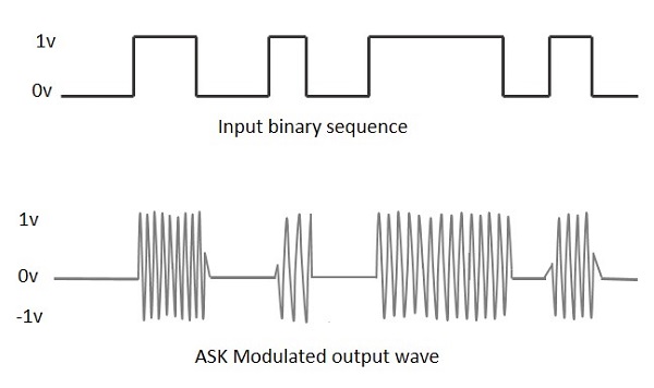
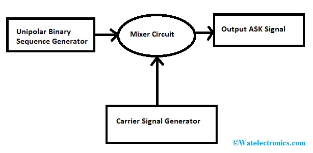
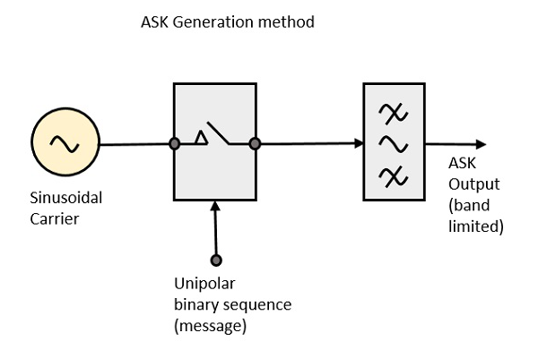
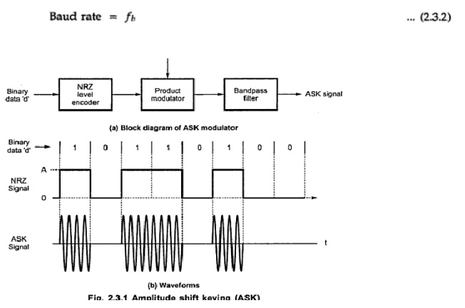
The carrier generator sends a continuous high-frequency carrier. ASK Modulator It consists of the carrier signal generator the binary sequence from the message signal and the band-limited filter. The predictor circuit is eliminated here and hence no assumed input is given to the demodulator. Figure 63 Circuit diagram of ASK asynchronous detector 2. As shown in the figure binary 1 will be represented by carrier signal with some amplitude while binary 0 will be represented by carrier of zero amplitudeie. 1 In the transmitter the precoder performs level conversion and then encodes the incoming data into groups of bits that modulate an analog carrier.
 Source: evalidate.in
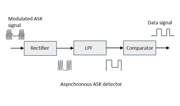
Figure 7 Block diagram of asynchronous ASK detector Figure 8 is the circuit diagram of asynchronous ASK detector which R1 R2 and μA741 comprise an inverting amplifier to amplify the input signal. The predictor circuit is eliminated here and hence no assumed input is given to the demodulator. The figure depicts operation of ASK modulation. It is clear from the block diagram given at the top that it is a type of digital modulation. Amplitude Modulation AM Frequency Modulation FM and Phase Modulation PM are the examples of Continuous Wave CW modulation while Amplitude Shift Keying ASK Frequency Shift Keying FSK and Phase Shift Keying PSK are examples of Digital Modulation Techniques.
 Source: watelectronics.com
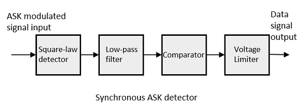
2 to ease in transmission the data clock recovery LESSON 981. Amplitude Modulation AM Frequency Modulation FM and Phase Modulation PM are the examples of Continuous Wave CW modulation while Amplitude Shift Keying ASK Frequency Shift Keying FSK and Phase Shift Keying PSK are examples of Digital Modulation Techniques. This experiment utilizes the structure of square-law detector and the block diagram is shown in figure 64. Figure 63 Circuit diagram of ASK asynchronous detector 2. The binary sequence from the message signal makes the unipolar input to be either High or Low.
 Source: watelectronics.com
As shown in the GRC block diagram of ASK we have multiplied the message signal ie. However there can be multiple levels of signal elements as well. As shown in the GRC block diagram of ASK we have multiplied the message signal ie. As a result the tune line voltage to the vco varies and this variation is proportional to the modulation done to the fm carrier wave. The carrier generator sends a continuous high-frequency carrier.
 Source: equestionanswers.com
As shown in the GRC block diagram of ASK we have multiplied the message signal ie. When the ASK signal pass through the rectifier we can obtain the positive half wave signal. This is a DSB transmitter. Figure 2-1 shows a simplified block diagram for a digital modulation system. The predictor circuit is eliminated here and hence no assumed input is given to the demodulator.
 Source: tutorialspoint.com
That is the signals here are sampled and sent in pulse form. A common feature among other techniques is that pulse code modulation also uses sampling technique. St A2 cos2πfct for Binary Logic-1 s. That is the signals here are sampled and sent in pulse form. The input is the delta modulated waveform which in fact consists of 0 or 1 which means delta or delta.
 Source: electronicscoach.com
Only the presence or absence of a sinusoid in a given time interval needs to be determined advantage. ASK Modulator It consists of the carrier signal generator the binary sequence from the message signal and the band-limited filter. It can be divided into 4 stages. Fig1 ASK Modulation ASK modulation can be represented by following equation. St A2 cos2πfct for Binary Logic-1 s.

ASK Modulation Technique The block diagram of the proposed FSO system using ASK modulation tech-nique is shown in Figure 1. Amplitude Modulation AM Frequency Modulation FM and Phase Modulation PM are the examples of Continuous Wave CW modulation while Amplitude Shift Keying ASK Frequency Shift Keying FSK and Phase Shift Keying PSK are examples of Digital Modulation Techniques. Amplitude shift keying ASK is produced. Figure 7 Block diagram of asynchronous ASK detector Figure 8 is the circuit diagram of asynchronous ASK detector which R1 R2 and μA741 comprise an inverting amplifier to amplify the input signal. It is clear from the block diagram given at the top that it is a type of digital modulation.
 Source: tutorialspoint.com
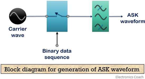
Fig1 ASK Modulation ASK modulation can be represented by following equation. ASK FSK PSK and QAM are all forms ofdigital modulation. ASK Modulator It consists of the carrier signal generator the binary sequence from the message signal and the band-limited filter. Figure 11-4 The basic block diagram of ASK modulator. 11 Fm Demodulator Block Diagram.
 Source: elprocus.com
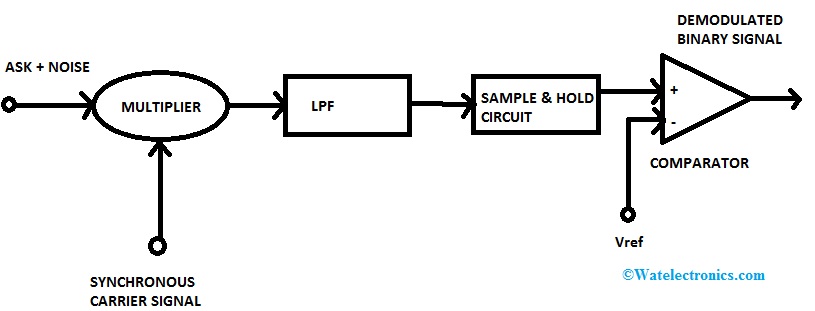
Here pulse generator encodes the digital data of bit se-. X ASK t A i cosW c tØ. The carrier generator sends a continuous high-frequency carrier. We have mentioned before that we can use synchronous detector to design the ASK demodulation. Figure 12-2 is the block diagram of asynchronous ASK detector.
 Source: tutorialspoint.com
First stage is trans-mitter which contains an optical source bit sequence generator pulse generator and AM modulator. The block diagram of the Delta Modulation receiver consists of a low pass filterLPF a summer and a delay circuit. 4-PSK MODULATION I Theory Figure below shows the block diagram of the mathematical implementation of 4-PSK. 11 Fm Demodulator Block Diagram. Only the presence or absence of a sinusoid in a given time interval needs to be determined advantage.

This type of modulation is different from all modulations learnt so far. 21 Figure 2-1 shows a simplified block diagram for a digital modulation system. Refer to the block diagram of Figure 3. ASK is very susceptible to. 2 In the transmitter the precoder performs level conversion and.
 Source: researchgate.net
Amplitude shift keying ASK is produced. First stage is trans-mitter which contains an optical source bit sequence generator pulse generator and AM modulator. 2 to ease in transmission the data clock recovery LESSON 981. 21 Figure 2-1 shows a simplified block diagram for a digital modulation system. Ht f is the carrier signal for the transmission hc f is the impulse response of the channel.

ASK Modulator The ASK modulator block diagram comprises of the carrier signal generator the binary sequence from the message signal and the band-limited filter. Modulation of Digital Data. Fig1 ASK Modulation ASK modulation can be represented by following equation. As a result the tune line voltage to the vco varies and this variation is proportional to the modulation done to the fm carrier wave. Ht f is the carrier signal for the transmission hc f is the impulse response of the channel.
 Source: electronicspost.com
A common feature among other techniques is that pulse code modulation also uses sampling technique. The input is the delta modulated waveform which in fact consists of 0 or 1 which means delta or delta. The carrier generator sends a continuous high-frequency carrier. Figure 7 Block diagram of asynchronous ASK detector Figure 8 is the circuit diagram of asynchronous ASK detector which R1 R2 and μA741 comprise an inverting amplifier to amplify the input signal. Modulation of Digital Data.
 Source: tutorialspoint.com
This is a DSB transmitter. The predictor circuit is eliminated here and hence no assumed input is given to the demodulator. Figure 12-2 is the block diagram of asynchronous ASK detector. 21 Figure 2-1 shows a simplified block diagram for a digital modulation system. The following notation is used.
 Source: elprocus.com
This structure is a typical asynchronous ASK detector. Amplitude Modulation AM Frequency Modulation FM and Phase Modulation PM are the examples of Continuous Wave CW modulation while Amplitude Shift Keying ASK Frequency Shift Keying FSK and Phase Shift Keying PSK are examples of Digital Modulation Techniques. If the frequency f is varied proportional to the information signal. That is the signals here are sampled and sent in pulse form. The predictor circuit is eliminated here and hence no assumed input is given to the demodulator.
 Source: elprocus.com
1 In the transmitter the precoder performs level conversion and then encodes the incoming data into groups of bits that modulate an analog carrier. The block diagram of the Delta Modulation receiver consists of a low pass filterLPF a summer and a delay circuit. 2 to ease in transmission the data clock recovery LESSON 981. Modulation of Digital Data. 11 Fm Demodulator Block Diagram.
 Source: brainkart.com
ASK is very susceptible to. The input is the delta modulated waveform which in fact consists of 0 or 1 which means delta or delta. Amplitude Modulation AM Frequency Modulation FM and Phase Modulation PM are the examples of Continuous Wave CW modulation while Amplitude Shift Keying ASK Frequency Shift Keying FSK and Phase Shift Keying PSK are examples of Digital Modulation Techniques. If the frequency f is varied proportional to the information signal. 4-PSK MODULATION I Theory Figure below shows the block diagram of the mathematical implementation of 4-PSK.
This site is an open community for users to submit their favorite wallpapers on the internet, all images or pictures in this website are for personal wallpaper use only, it is stricly prohibited to use this wallpaper for commercial purposes, if you are the author and find this image is shared without your permission, please kindly raise a DMCA report to Us.
If you find this site good, please support us by sharing this posts to your favorite social media accounts like Facebook, Instagram and so on or you can also bookmark this blog page with the title block diagram of ask modulation by using Ctrl + D for devices a laptop with a Windows operating system or Command + D for laptops with an Apple operating system. If you use a smartphone, you can also use the drawer menu of the browser you are using. Whether it’s a Windows, Mac, iOS or Android operating system, you will still be able to bookmark this website.