Block diagram of frequency synthesizer
Home » Background » Block diagram of frequency synthesizerYour Block diagram of frequency synthesizer images are ready in this website. Block diagram of frequency synthesizer are a topic that is being searched for and liked by netizens now. You can Find and Download the Block diagram of frequency synthesizer files here. Get all royalty-free vectors.
If you’re looking for block diagram of frequency synthesizer pictures information related to the block diagram of frequency synthesizer interest, you have come to the right blog. Our site always gives you suggestions for seeking the maximum quality video and picture content, please kindly search and locate more enlightening video content and images that fit your interests.
Block Diagram Of Frequency Synthesizer. 5V is the input to the board and is required for the opamp. Then that charge speed. Quency stability determines the sensitivity and bit error rate BER of the system. The free-running frequency of the PLL is set to 20 kHz.
 Block Diagram Of Proposed Digital Fractional N Frequency Synthesizer Download Scientific Diagram From researchgate.net
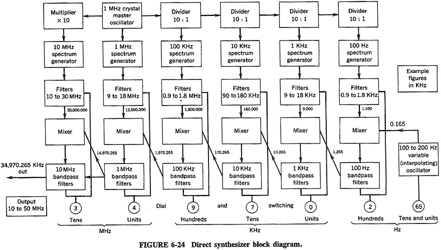
It can be seen from the block diagram that the circuit is repeated for each switch and the repeated circuit are required whenever decade is added. The synthesizer is excited with a 5 kHz signal Input 1. Basic digital frequency synthesizer block diagram As a result of the performance and capabilities they provide frequency synthesizers are a common form of RF building block and the RF circuit design is often simplified by the fact that many frequency synthesizer ICs are available with standard RF circuit designs that can be tailored to suit the exact requirement. 2 It uses PLL circuits and mixer. Parallel output from Counter 1 is connected to Register input and Register output is connected to preset. Niknejad PLLs and Frequency Synthesis.
According to the ADF4106 data.
33V is needed for ADF4002. Choose a higher frequency synthesizer than is required. Describe the alignment procedures unique to FM receivers. Figure 1 shows a block diagram of the CDCE72010. Along with good phase noise performance the frequency synthesizer also needs to be. PLL Frequency Synthesizer block diagram.
 Source: researchgate.net
2 It uses PLL circuits and mixer. Together with an external VCXO and loop filter the device completes a PLL. 1 The synthesizer is used for developing all the signals used by the transmitter and Receiver. Now we can draft a very simplified block diagram sketch like the one shown in Figure 28 which helps to quickly estimate some key design characteristics such as phase noise loop bandwidth and tuning speed. Trace the signal flow through FM stereo and SCA decoder circuits.
 Source: researchgate.net
Trace the signal flow through FM stereo and SCA decoder circuits. The black lines are waveform signals while the colored lines represent different control signals. And therefore new frequency synthesizer was developed. Together with an external VCXO and loop filter the device completes a PLL. 33V is needed for ADF4002.
 Source: mdpi.com
1 there is a block diagram of the digital frequency synthesizer 2. CDCE72010 Block Diagram As shown in Figure 1 the CDCE72010 has internal dividers a phase frequency detector charge pump and LVPECLLVDSLVCMOS input and output buffers. The block diagram of the proposed PLL Frequency synthesizer is shown in Figure1 10 11. Quency stability determines the sensitivity and bit error rate BER of the system. 5V is the input to the board and is required for the opamp.
 Source: researchgate.net
2 It uses PLL circuits and mixer. In the example shown an ADF4xxx synthesizer is used with an external filter and VCO. According to the ADF4106 data. It consist of Counter 1 which count up frequency fC1 gated by input frequency fX. It can be seen from the block diagram that the circuit is repeated for each switch and the repeated circuit are required whenever decade is added.
 Source: eeeguide.com
33V is needed for ADF4002. Operating under the same conditions at 900 MHz the ADF4106 will give 6-dB better phase noise than the ADF4111 see Table 1. Along with good phase noise performance the frequency synthesizer also needs to be. Draw a block diagram of a frequency-synthesized FM receiver. Block diagram of frequency synthesizer test board interfaced to VCO.

If there is a phase difference between the two signals then PFD generate the UP and DOWN signals. Trace the signal flow through FM stereo and SCA decoder circuits. The high frequency VCO tracks the stable low frequency reference in frequency and. Components include a VCO a frequency divider a phase detector PD and a loop lter. Along with good phase noise performance the frequency synthesizer also needs to be.
 Source: electronicproducts.com
In the example shown an ADF4xxx synthesizer is used with an external filter and VCO. If there is a phase difference between the two signals then PFD generate the UP and DOWN signals. Basic digital frequency synthesizer block diagram As a result of the performance and capabilities they provide frequency synthesizers are a common form of RF building block and the RF circuit design is often simplified by the fact that many frequency synthesizer ICs are available with standard RF circuit designs that can be tailored to suit the exact requirement. The block diagram of the proposed PLL Frequency synthesizer is shown in Figure1 10 11. Block diagram of the proposed architecture 2 FUNCTIONAL DESCRIPTION In the Fig.
 Source: researchgate.net
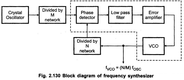
Block Diagram The RF frequency synthesizer is a negative feedback control system which consists of a referencephase frequency detector PFD charge pump loop filter voltage controlled oscillator VCO N counter and RF output dividermultiplier Figure 1. Basic digital frequency synthesizer block diagram As a result of the performance and capabilities they provide frequency synthesizers are a common form of RF building block and the RF circuit design is often simplified by the fact that many frequency synthesizer ICs are available with standard RF circuit designs that can be tailored to suit the exact requirement. 1 there is a block diagram of the digital frequency synthesizer 2. These signal increasedecrease the charge on filter. Suppose that synthesizer is controlled by microcontroller by Ctr1 control of pulse swallowing and Ctr2 calculated average value of signal from generator G.
 Source: eeeguide.com
Choose a higher frequency synthesizer than is required. Basic digital frequency synthesizer block diagram As a result of the performance and capabilities they provide frequency synthesizers are a common form of RF building block and the RF circuit design is often simplified by the fact that many frequency synthesizer ICs are available with standard RF circuit designs that can be tailored to suit the exact requirement. And therefore new frequency synthesizer was developed. The block diagram of a frequency synthesizer consisting of a Phase Locked Loop PLL and a divide-by-𝑁 counter comprising 2 4 8 16 outputs is sketched below. Block Diagram of CORDIC based DDFS 5 Implementation and experimental results Simulations are done with FTW of 32 bits and clock frequency of 200M Hz by changing the phase width of wave with an amplitude width of 12 and 16 bits each.
 Source: researchgate.net
Apply basic troubleshooting methods to FM receivers. It consist of Counter 1 which count up frequency fC1 gated by input frequency fX. 2 It uses PLL circuits and mixer. The black lines are waveform signals while the colored lines represent different control signals. Block Diagram of CORDIC based DDFS 5 Implementation and experimental results Simulations are done with FTW of 32 bits and clock frequency of 200M Hz by changing the phase width of wave with an amplitude width of 12 and 16 bits each.
 Source: eeeguide.com
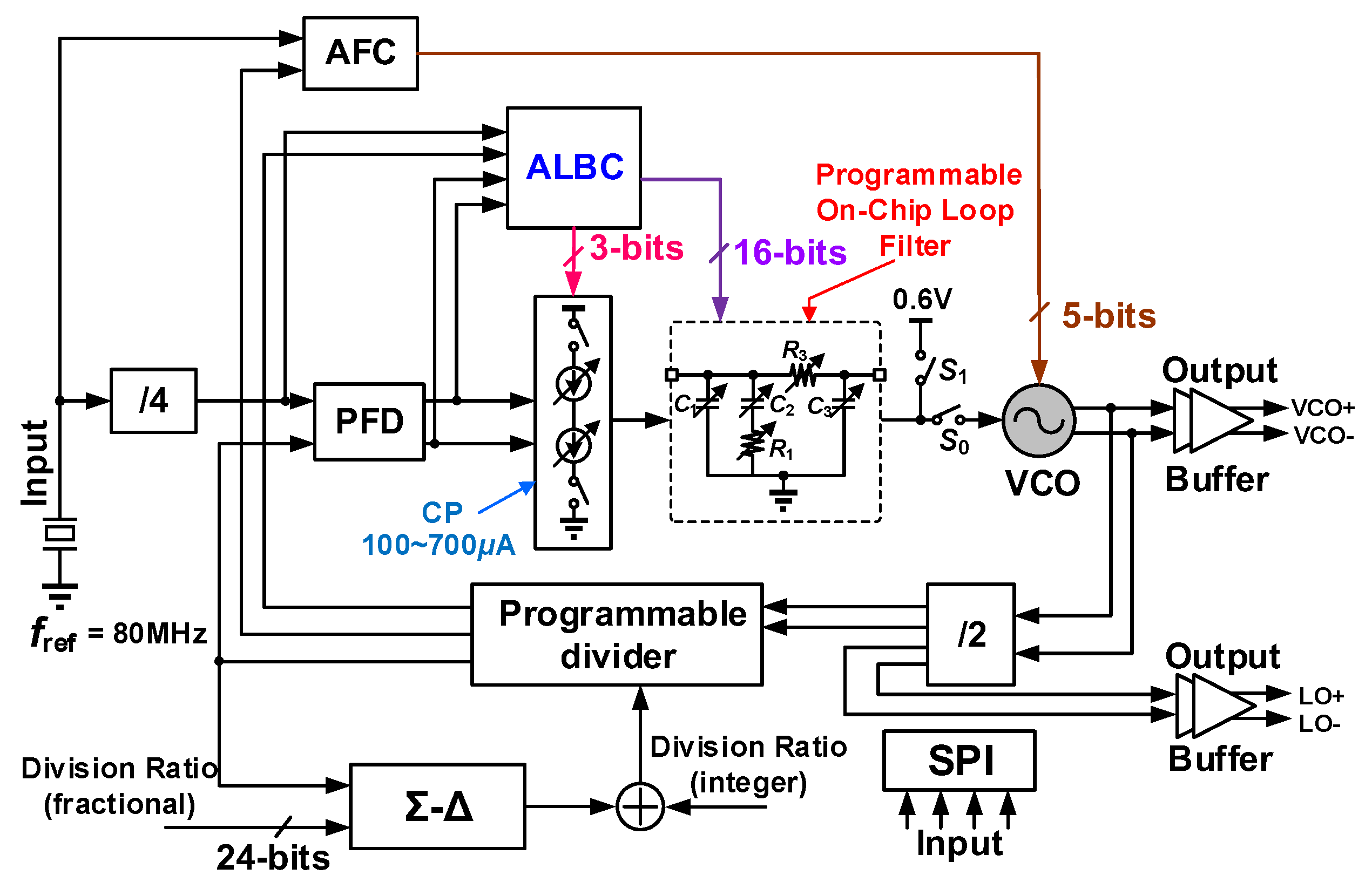
When applied to 60 GHz systems designing the frequency. Synthesizer block for such high frequency is a challenge since its phase noise and fre-. 5V is the input to the board and is required for the opamp. The RF frequency synthesizer is a negative feedback control system which consists of a reference phase frequency detector PFD charge pump loop filter voltage controlled oscillator VCO N counter and RF output dividermultiplier Figure 1. It is N-integer architecture it comprises one phase-frequency detectors PFD and charge pump CP a passive low pass loop filter current starve VCO a fully programmable dual-modulus frequency divider with Programmable counter and swallow counter.
 Source: chegg.com
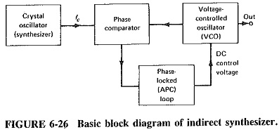
4 The function of PLL is to lock or synchronize frequency of VCO to that of input signal. 4 The function of PLL is to lock or synchronize frequency of VCO to that of input signal. The ADF4106 frequency synthesizer can be used to implement local oscillators in the up-conversion and down-conversion sections of wireless receivers and transmitters. Niknejad PLLs and Frequency Synthesis. Choose a higher frequency synthesizer than is required.
 Source: slideshare.net
PLL Frequency Synthesizer block diagram. This could come from your VCO board which has the 5V regulator chip on it then only one power supply input 9V would be needed. 2 It uses PLL circuits and mixer. When applied to 60 GHz systems designing the frequency. CDCE72010 Block Diagram As shown in Figure 1 the CDCE72010 has internal dividers a phase frequency detector charge pump and LVPECLLVDSLVCMOS input and output buffers.
 Source: chegg.com
Quency stability determines the sensitivity and bit error rate BER of the system. 1 there is a block diagram of the digital frequency synthesizer 2. Phase Locked Loop Block Diagram ÖN Ref Div Loop Filter VCO Phase Locked Loops PLL are ubiquitous circuits used in countless communication and engineering applications. The black lines are waveform signals while the colored lines represent different control signals. Note that analog synthesizers are inherently modular and thus this block diagram only represents one such.
 Source: ques10.com
Block diagram of a PLL. Block Diagram of a Typical Patch on an Analog Synthesizer. These signal increasedecrease the charge on filter. Then that charge speed. Note that analog synthesizers are inherently modular and thus this block diagram only represents one such.
 Source: researchgate.net
These signal increasedecrease the charge on filter. And therefore new frequency synthesizer was developed. Block diagram of frequency synthesizer test board interfaced to VCO. Choose a higher frequency synthesizer than is required. Block Diagram of CORDIC based DDFS 5 Implementation and experimental results Simulations are done with FTW of 32 bits and clock frequency of 200M Hz by changing the phase width of wave with an amplitude width of 12 and 16 bits each.
 Source: wikiwand.com
According to the ADF4106 data. Frequency is scaled by the use of counters. Bandwidth synthesizers since the VCO tuning sensitivity and the loop division coefficients may change with frequency. Quency stability determines the sensitivity and bit error rate BER of the system. Note that analog synthesizers are inherently modular and thus this block diagram only represents one such.
 Source: researchgate.net
Draw a block diagram of a frequency-synthesized FM receiver. The RF frequency synthesizer is a negative feedback control system which consists of a reference phase frequency detector PFD charge pump loop filter voltage controlled oscillator VCO N counter and RF output dividermultiplier Figure 1. Basic digital frequency synthesizer block diagram As a result of the performance and capabilities they provide frequency synthesizers are a common form of RF building block and the RF circuit design is often simplified by the fact that many frequency synthesizer ICs are available with standard RF circuit designs that can be tailored to suit the exact requirement. Now we can draft a very simplified block diagram sketch like the one shown in Figure 28 which helps to quickly estimate some key design characteristics such as phase noise loop bandwidth and tuning speed. This could come from your VCO board which has the 5V regulator chip on it then only one power supply input 9V would be needed.
This site is an open community for users to do submittion their favorite wallpapers on the internet, all images or pictures in this website are for personal wallpaper use only, it is stricly prohibited to use this wallpaper for commercial purposes, if you are the author and find this image is shared without your permission, please kindly raise a DMCA report to Us.
If you find this site helpful, please support us by sharing this posts to your own social media accounts like Facebook, Instagram and so on or you can also save this blog page with the title block diagram of frequency synthesizer by using Ctrl + D for devices a laptop with a Windows operating system or Command + D for laptops with an Apple operating system. If you use a smartphone, you can also use the drawer menu of the browser you are using. Whether it’s a Windows, Mac, iOS or Android operating system, you will still be able to bookmark this website.