Block diagram of ir spectroscopy
Home » Wallpapers » Block diagram of ir spectroscopyYour Block diagram of ir spectroscopy images are ready in this website. Block diagram of ir spectroscopy are a topic that is being searched for and liked by netizens now. You can Download the Block diagram of ir spectroscopy files here. Download all royalty-free images.
If you’re searching for block diagram of ir spectroscopy images information connected with to the block diagram of ir spectroscopy interest, you have pay a visit to the ideal site. Our website always provides you with hints for seeking the highest quality video and image content, please kindly search and find more enlightening video content and graphics that match your interests.
Block Diagram Of Ir Spectroscopy. Draw block diagram of IR spectrophotometer and describe the basic components. A Rotating mirror B Collimating mirror. Raman spectroscopy is a vibrational spectroscopic tech-nique that can be used to optically probe the molecular changesassociatedwithdiseasedtissuesTheobjectiveofour study was to explore near-infrared NIR Raman spectros-copy for distinguishing tumor from normal bronchial tissue. Of the electromagnetic spectrum which includes such other forms of radiation as radio infrared IR cosmic and X rays see Figure 1.
 A Schematic Diagram Of A Dispersive Infrared Spectrometer 6 Download Scientific Diagram From researchgate.net
Ion Selective Electrodes-Principle and Types. Figure 1 The electromagnetic spectrum Frequency Hz Wavelength m Ultraviolet Visible Infrared. Mechanism of Electrospray Ionization ESI Charged Capillary Needle Heated Capillary 3-8 kV. 0 20 40 60 80 100. Introduction to UV Visible Spectrometers. Instrumentation of X-Ray Spectroscopy.
This unit is a product of the Fourier transform algorithm operating on the interferogram and is the reciprocal of the actual wavelength of light measured in centimeters at a point in the infrared spectrum.
Thermal block diagram of a microbolometer listing the key parts and the physical quantities that govern the microbolometer behavior. It is based on absorption spectroscopy 5. 400 600 800 1000 1200 1400 1600 1800mz. Absorption Instrumentation and Block Diagram Representation more Online Exam Quiz. Flame Photometry- Principle Instrumentation Block diagram only Yes 25. A FTIR uses an interferometer to measure all IR frequencies simultaneously and produces an interferogram2 The interferogram is operated on mathematically by a Fourier Transformation outputting an absorption or transmittance spectrum.
 Source: studymafia.org
λ cf where c velocity of the wave. Figure 226 shows a schematic of a FTIR spectrometer. Thermal block diagram of a microbolometer listing the key parts and the physical quantities that govern the microbolometer behavior. There are however advantages to be gained from measurement in the time domain followed by computer transformation into the frequency domain. IR Spectroscopy - Principles instrumentation and Applications No 22.

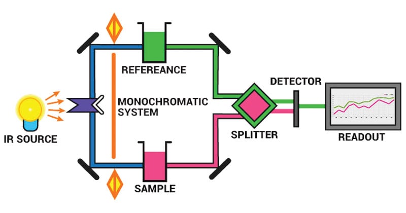
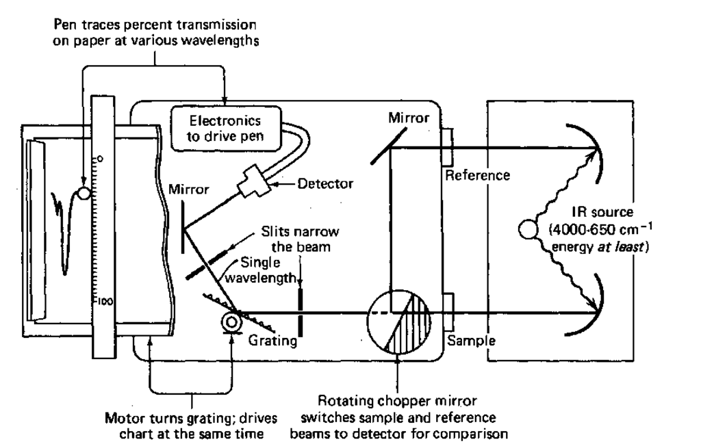
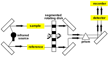
Simplified representation of a dispersive IR spectrometer. Figure 226 shows a schematic of a FTIR spectrometer. Instrumentation of ESR Spectrometer. A basic thermal block diagram of such bolometer is shown in Figure 121. The light source the.

Thermal capacitance thermal conductance incident power temperature of pixel and heat sink. Electromagnetic spectrum and light spectrum Wavelength λ is inversely related to frequency f. A blackbody source emits IR radiation over a range of wavenumbers typically between 4000 and 400 cm 1 for fire gas analysis. For near-IR systems the lamp can be replaced with the new broadband emitter B. So what is FTIR.
 Source: youtube.com
The overtone region begins at about 12500 cm-1 08 m. A basic thermal block diagram of such bolometer is shown in Figure 121. A block diagram of a classic dispersive IR spectrometer is shown in Figure PageIndex1. Instrumentation of ESR Spectrometer. Atomic Absorption Spectroscopy- Principle.
 Source: researchgate.net
A blackbody source emits IR radiation over a range of wavenumbers typically between 4000 and 400 cm 1 for fire gas analysis. Mass spectroscopy determining molecular weight structural elements molecular formula The various spectroscopies are the primary method for determining the structure of compounds. Various regions in the Infrared spectrum Wavelengths that are longer than those for the visible region are referred to as the near infrared. λ is measured in microns µm. For near-IR systems the lamp can be replaced with the new broadband emitter B.
 Source: microbenotes.com
The IR beams passes through an interferometer which consists of a beam splitter a fixed mirror and a moving mirror. For example the quantitative analysis of transition metal ions can be achieved with the help of UV-Visible spectroscopy. Infrared Thermometry Understanding and using the Infrared Thermometer Electromagnetic Spectrum. IR Spectroscopy - Principles instrumentation and Applications No 22. The usefulness of infrared spectroscopy arises because different chemical structures molecules produce different spectral fingerprints.
 Source: what-when-how.com
Instrumentation for Electron Spectroscopy. The usefulness of infrared spectroscopy arises because different chemical structures molecules produce different spectral fingerprints. The overtone region begins at about 12500 cm-1 08 m. The mass analyzer is the heart of the mass spectrometer. Ion Source Mass Analyzer Detector High Vacuum.
 Source: ausetute.com.au
Thermal block diagram of a microbolometer listing the key parts and the physical quantities that govern the microbolometer behavior. A blackbody source emits IR radiation over a range of wavenumbers typically between 4000 and 400 cm 1 for fire gas analysis. The Fourier Transform converts the detector output to an interpretable spectrum. Schematic of an FT-IR using a Michelson interferometer. 1 µm 10-6m.
 Source: sciencedirect.com
System components There are several key components of such a system. The usefulness of infrared spectroscopy arises because different chemical structures molecules produce different spectral fingerprints. For near-IR systems the lamp can be replaced with the new broadband emitter B. Figure 1 The electromagnetic spectrum Frequency Hz Wavelength m Ultraviolet Visible Infrared. A basic thermal block diagram of such bolometer is shown in Figure 121.

The usefulness of infrared spectroscopy arises because different chemical structures molecules produce different spectral fingerprints. Infrared Thermometry Understanding and using the Infrared Thermometer Electromagnetic Spectrum. IR Spectroscopy - Principles instrumentation and Applications No 22. UV-Visible spectroscopy is widely used in the field of analytical chemistry especially during the quantitative analysis of a specific analyte. Figure 1 The electromagnetic spectrum Frequency Hz Wavelength m Ultraviolet Visible Infrared.
 Source: youtube.com
Ion Source Mass Analyzer Detector High Vacuum. The Fourier Transform converts the detector output to an interpretable spectrum. Explanation of Finger Print Region No 23. 1 µm 10-6m. λ is measured in microns µm.
 Source: researchgate.net
Simplified representation of a dispersive IR spectrometer. Block diagram of IR spectrometer Schematic of IR Spectrometers Interferometer based Figure 2. 400 600 800 1000 1200 1400 1600 1800mz. The inlet transfers the sample into the vacuum of the mass spectrometer. Thermal block diagram of a microbolometer listing the key parts and the physical quantities that govern the microbolometer behavior.
 Source: researchgate.net
Of the electromagnetic spectrum which includes such other forms of radiation as radio infrared IR cosmic and X rays see Figure 1. The x-axis of the FT-IR spectrum is typically displayed in wavenumbers or cm-1. Of the electromagnetic spectrum which includes such other forms of radiation as radio infrared IR cosmic and X rays see Figure 1. λ cf where c velocity of the wave. Introduction to UV Visible Spectrometers.
 Source: link.springer.com
Introduction to UV Visible Spectrometers. For near-IR systems the lamp can be replaced with the new broadband emitter B. Figure C Dispersive IR instruments operate in the frequency domain. If the molecule is not too large or complex the determination should be very accurate. The Fourier Transform converts the detector output to an interpretable spectrum.
 Source: researchgate.net
This unit is a product of the Fourier transform algorithm operating on the interferogram and is the reciprocal of the actual wavelength of light measured in centimeters at a point in the infrared spectrum. Estimation of Sodium by Flame Photometry No. Each frequency that passes through the sample is measured individually by the detector which consequently slows the process of scanning the entire IR region. Figure 1 The electromagnetic spectrum Frequency Hz Wavelength m Ultraviolet Visible Infrared. λ cf where c velocity of the wave.
 Source: researchgate.net
Raman spectroscopy is a vibrational spectroscopic tech-nique that can be used to optically probe the molecular changesassociatedwithdiseasedtissuesTheobjectiveofour study was to explore near-infrared NIR Raman spectros-copy for distinguishing tumor from normal bronchial tissue. There are however advantages to be gained from measurement in the time domain followed by computer transformation into the frequency domain. It is based on absorption spectroscopy 5. Figure 1 The electromagnetic spectrum Frequency Hz Wavelength m Ultraviolet Visible Infrared. Infrared spectroscopy IR spectroscopy is the spectroscopy that deals with the infrared region of the electromagnetic spectrum that is light with a longer wavelength and lower frequency than visible light Infrared Spectroscopy is the analysis of infrared light interacting with a molecule.
 Source: bruker.com
The Fourier Transform converts the detector output to an interpretable spectrum. Flame Photometry- Principle Instrumentation Block diagram only Yes 25. Estimation of Iron by Colorimetry Block diagram only No 24. Thermal block diagram of a microbolometer listing the key parts and the physical quantities that govern the microbolometer behavior. A basic thermal block diagram of such bolometer is shown in Figure 121.
 Source: chem.libretexts.org
1 µm 10-6m. 2 A detailed instrumental diagram of a single beam FTIR is shown in Figure 21 An IR source in the near. It is based on absorption spectroscopy 5. UV-Visible spectroscopy is widely used in the field of analytical chemistry especially during the quantitative analysis of a specific analyte. The various components of a double-monochromator infrared spectrophotometer shown in Figure 223 are as follows below.
This site is an open community for users to do sharing their favorite wallpapers on the internet, all images or pictures in this website are for personal wallpaper use only, it is stricly prohibited to use this wallpaper for commercial purposes, if you are the author and find this image is shared without your permission, please kindly raise a DMCA report to Us.
If you find this site beneficial, please support us by sharing this posts to your own social media accounts like Facebook, Instagram and so on or you can also bookmark this blog page with the title block diagram of ir spectroscopy by using Ctrl + D for devices a laptop with a Windows operating system or Command + D for laptops with an Apple operating system. If you use a smartphone, you can also use the drawer menu of the browser you are using. Whether it’s a Windows, Mac, iOS or Android operating system, you will still be able to bookmark this website.