Block diagram of radar receiver
Home » Background » Block diagram of radar receiverYour Block diagram of radar receiver images are ready. Block diagram of radar receiver are a topic that is being searched for and liked by netizens now. You can Get the Block diagram of radar receiver files here. Find and Download all free photos and vectors.
If you’re searching for block diagram of radar receiver pictures information connected with to the block diagram of radar receiver topic, you have pay a visit to the right blog. Our website frequently gives you suggestions for seeking the highest quality video and image content, please kindly search and locate more informative video content and graphics that fit your interests.
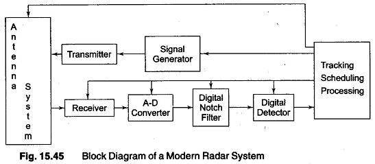
Block Diagram Of Radar Receiver. The intermediate frequency and the bandwidth required in FM are higher than that in AM receivers. 61 represents a typical meteorological Doppler radar receiver. Many units measure only. The figure below shows the block diagram representation of radar.
 Functional Block Diagram Of Multi Band Passive Bistatic Radar Download Scientific Diagram From researchgate.net
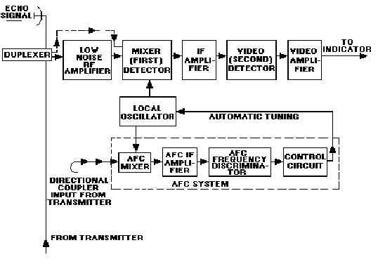
This block diagram may be used for your own lessons but there are no block labels in the animation and there is no background image landscape. 2-18 GHz Radar Warning Receiver Each PDW is transferred in 8 clock cycles. There are different kinds of versions available for the radar range equations. Signals from the antenna enter the receiver via the duplexer. 6-6. Let us now see the function of each block of Pulse Radar.
High Power Transmit Sections 100s of W to 1s MW Low Power Transmit.
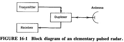
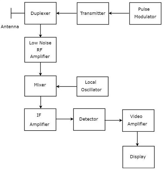
Basic Radar System Block Diagram consists of a transmitter and a receiver each connected to a directional antenna. In this chapter let us discuss the working of Pulse Radar. The output of the mixer is applied to the IF amplifier stages. All frequencies and clock pulses are derived from the highly stable frequency of a master oscillator and these signals therefore have a phase reference stable to each other. A typical superheterodyne radar receiver is shown in figure 2-23. The diagram illustrates a full transfer plus the start of the next transfer.
 Source: electriciantraining.tpub.com
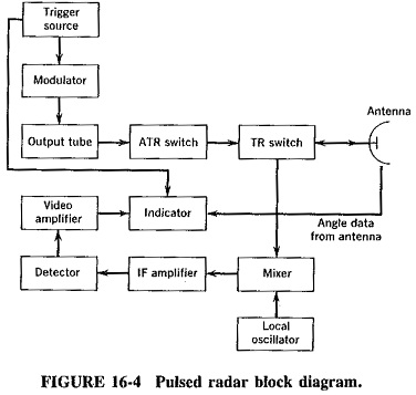
Some models are single units and some are two or more pieces boxes andor have multiple antennas. Block Diagram Showing CW RADAR Radar Range Equation. In this block diagram of monostatic radar you can see that it has an indicator a transmitter and receiver a duplexer and a single antenna. Each Word block represents a portion of PDW data. 61 represents a typical meteorological Doppler radar receiver.
 Source: researchgate.net
Functional block diagram of a front-end linear receiver for weather radar The block diagram shown here is a fully coherent radar. Universal Block Diagram of Pulse Radar. In this block diagram of monostatic radar you can see that it has an indicator a transmitter and receiver a duplexer and a single antenna. MS-PowerPoint with text boxes in your own language version. As you can see in this block diagram that monostatic radar uses only one antenna for transmission and reception purpose thats why it is known as monostatic radar Mono means single and bi means double.
 Source: eeeguide.com
Radar History Radio Detection And Ranging Hertz. Radar transmitter and receiver can be divided into two important subsystems High power transmitter sections Low power sections Radar waveform generator and receiver Duplexer. FM demodulation is totally different from AM demodulation. It can also be a power oscillator such as magnetron. The block diagram in Fig.

The final element in the superheterodyne receiver block diagram is shown as an audio amplifier although this could be any form of circuit block that is used to process or amplified the demodulated signal. 2-18 GHz Radar Warning Receiver Each PDW is transferred in 8 clock cycles. These block labels can be placed in an own layer over the animation in eg. The transmitter is capable of sending out a large UHF or microwave power through the antenna. Signals from the antenna enter the receiver via the duplexer.
 Source: researchgate.net
And both the sections perform their respective operation. Block Diagram of Radar System. B-1 where Aext external attenuation dB as shown in Figure 1 Pp peak power produced by the radar transmitter dBm Lc loss through the coupler dB Ain attenuation provided internally at the measurement device front end input dB. The mixer has exactly the same function as the synchronous detector in Fig. Many units measure only.
 Source: electronicsdesk.com
Two IF amplifier stages are often provided. B-1 where Aext external attenuation dB as shown in Figure 1 Pp peak power produced by the radar transmitter dBm Lc loss through the coupler dB Ain attenuation provided internally at the measurement device front end input dB. The advantage of imaging radar systems is the ability to see through clouds fog rain and darkness. Radar Block Diagram This receiver is a superheterodyne receiver because of the intermediate frequency IF amplifier. RF Sampling S-Band Radar Receiver 44 Receiver Performance After calculating the received power at the farthest distance for each signal the designer can determine the required noise performance of the receiver.
 Source: researchgate.net
By comparing the block diagrams Figure Above of the radar and transponder power supplies the similarities will be apparent. Phase-Lock Loop PLL Receiver. Let us now see the function of each block of Pulse Radar. Many units measure only. The block diagram in Fig.
 Source: msguide7.blogspot.com
BIT DataWords 12 DataWords 34 DataWords 34 0 Frequency 0 Pulse Width 0 Time of Arrival 0 1. RF Sampling S-Band Radar Receiver 44 Receiver Performance After calculating the received power at the farthest distance for each signal the designer can determine the required noise performance of the receiver. Universal Block Diagram of Pulse Radar. Many units measure only. Some models are for stationary use only and some are for both stationary and moving mode.

When the object is assumed to be in the middle of the antenna signal then the highest radar detection range can be written as. Many units measure only. A receiver of this type meets all the requirements listed above. And both the sections perform their respective operation. The transmitter is capable of sending out a large UHF or microwave power through the antenna.
 Source: researchgate.net
B-1 where Aext external attenuation dB as shown in Figure 1 Pp peak power produced by the radar transmitter dBm Lc loss through the coupler dB Ain attenuation provided internally at the measurement device front end input dB. Radar transmitter and receiver can be divided into two important subsystems High power transmitter sections Low power sections Radar waveform generator and receiver Duplexer. Imaging radar systems develop image maps of a region and are used to monitor climate weather conditions oil spills land use and many other things. Low power transmit and receive sections Radar waveform generator and. 31 except that here the output has a carrier frequency at the intermediate frequency IF whereas in Fig.
 Source: eeeguide.com
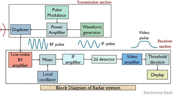
The figure below shows the block diagram representation of radar. Pulse Radar uses single Antenna for both transmitting and receiving of signals with the help of Duplexer. Radar systems can be classified into continuous wave CW Radar or a Pulsed Radar based on the. B-1 where Aext external attenuation dB as shown in Figure 1 Pp peak power produced by the radar transmitter dBm Lc loss through the coupler dB Ain attenuation provided internally at the measurement device front end input dB. In addition Block 4 controls the LO frequency transmitted by Block 2.
 Source: researchgate.net
And both the sections perform their respective operation. In addition Block 4 controls the LO frequency transmitted by Block 2. Two IF amplifier stages are often provided. Diagram the minimum decibel amount of attenuation A required will be. Low power transmit and receive sections Radar waveform generator and.
 Source: eeeguide.com
31 the output has no carrier it is a video signal. Following is the block diagram of Pulse Radar. The mixer has exactly the same function as the synchronous detector in Fig. By comparing the block diagrams Figure Above of the radar and transponder power supplies the similarities will be apparent. If the receiver output exceeds the threshold a signal is assumed to be present.
 Source: chegg.com
Block 1 mixes an analog RF signal with an analog LO frequency from Block 2 to produce an analog intermediate frequency IF. Following is the block diagram of Pulse Radar. Figure 6 shows a block diagram of the radar receiver. There are different kinds of versions available for the radar range equations. Some models are for stationary use only and some are for both stationary and moving mode.
 Source: tutorialspoint.com
Radar Block Diagram Radar Frequencies Radar Applications Related Problems 3. 2-18 GHz Radar Warning Receiver Each PDW is transferred in 8 clock cycles. Pulse Radar uses single Antenna for both transmitting and receiving of signals with the help of Duplexer. And both the sections perform their respective operation. Imaging radar systems develop image maps of a region and are used to monitor climate weather conditions oil spills land use and many other things.
 Source: researchgate.net
High Power Transmit Sections 100s of W to 1s MW Low Power Transmit. Similar to Figure 14 in Skolnik Coherent radar uses the same local oscillator reference for transmit and receive. When the object is assumed to be in the middle of the antenna signal then the highest radar detection range can be written as. These block labels can be placed in an own layer over the animation in eg. The output of the mixer is applied to the IF amplifier stages.
 Source: researchgate.net
The mixer has exactly the same function as the synchronous detector in Fig. This is called threshold detection. These block labels can be placed in an own layer over the animation in eg. Universal Block Diagram of Pulse Radar. By comparing the block diagrams Figure Above of the radar and transponder power supplies the similarities will be apparent.
 Source: researchgate.net
High Power Transmit Sections 100 W to MW Low Power Transmit Section 100mw to 1W Radar transmitter and receiver can be divided into two major subsystems. Similar to Figure 14 in Skolnik Coherent radar uses the same local oscillator reference for transmit and receive. As you can see in this block diagram that monostatic radar uses only one antenna for transmission and reception purpose thats why it is known as monostatic radar Mono means single and bi means double. High Power Transmit Sections 100s of W to 1s MW Low Power Transmit. All frequencies and clock pulses are derived from the highly stable frequency of a master oscillator and these signals therefore have a phase reference stable to each other.
This site is an open community for users to submit their favorite wallpapers on the internet, all images or pictures in this website are for personal wallpaper use only, it is stricly prohibited to use this wallpaper for commercial purposes, if you are the author and find this image is shared without your permission, please kindly raise a DMCA report to Us.
If you find this site value, please support us by sharing this posts to your own social media accounts like Facebook, Instagram and so on or you can also bookmark this blog page with the title block diagram of radar receiver by using Ctrl + D for devices a laptop with a Windows operating system or Command + D for laptops with an Apple operating system. If you use a smartphone, you can also use the drawer menu of the browser you are using. Whether it’s a Windows, Mac, iOS or Android operating system, you will still be able to bookmark this website.