Block diagram reduction method
Home » Background » Block diagram reduction methodYour Block diagram reduction method images are ready in this website. Block diagram reduction method are a topic that is being searched for and liked by netizens now. You can Get the Block diagram reduction method files here. Download all free photos.
If you’re looking for block diagram reduction method pictures information connected with to the block diagram reduction method interest, you have pay a visit to the ideal site. Our site frequently provides you with hints for downloading the maximum quality video and picture content, please kindly search and locate more enlightening video articles and images that fit your interests.
Block Diagram Reduction Method. Block Diagram Reduction W3 4Masons Rule and the Signal-Flow Graph A compact alternative notation to the block diagram is given by the signal-ow graph introduced Signal-ow by S. Block Diagram ReductionBy Tutorials Point India Private LimitedCheck out the latest courses on httpsbitly3roYkCgUse coupon YOUTUBE to get FLAT 10 OFF. Let us discuss these rules one by one for the reduction of the control system block diagram. Signal-Flow Graph Block diagram reduction is not convenient to a complicated system.
 Block Diagram Of Control Systems Transfer Functions Reduction Summing Points Electrical4u From electrical4u.com
Block Diagram Reduction Techniques Prepared by AParimala Gandhi APSSECE Department KITCBE CONTROL SYSTEM ENGINEERING 2. The method is validated with some examples including examples from some well-known textbooks in control. B1g1 successive reductions of the block diagram by relocating summing point A. Ratio between transformation of output to the transformation of input when all the initial conditions are zero. BLOCK DIAGRAM REDUCTION Block diagram is a pictorial representation of a control system showing inter-relation between the transfer function of various components. 31 Signal-Flow Graph only utilize two.
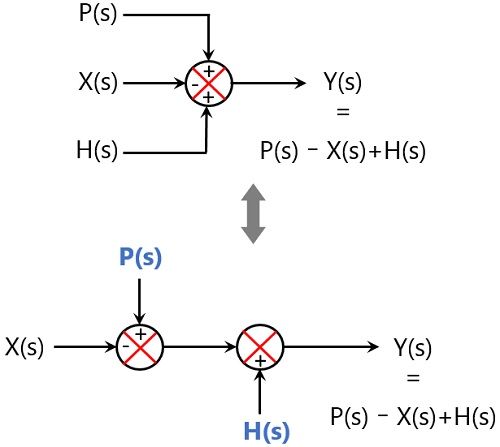
Try to shift take off points towards right and Summing point towards left.
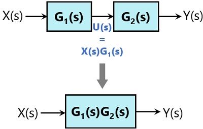
However in case of a complicated system the block diagram reduction technique becomes quite difficult as well as time-consuming. Combining two blocks into one gives Figure 3-33c. Figure 21 shows an element of the block diagram. Block Diagram Reduction Figure 1. For the successful implementation of this technique some rules for block diagram reduction to be followed. A block diagram consists of blocks that represent transfer functions of the different variables of interest.
 Source: electronicscoach.com
000 - Control Engineering Lecture Series007 - Block Diagram Reducti. Rules for reducing block diagram to find the transfer function About Press Copyright Contact us Creators Advertise Developers Terms Privacy Policy Safety How YouTube works Test new. A Block diagram of a dynamic system. Block Diagram Reduction Techniques Prepared by AParimala Gandhi APSSECE Department KITCBE CONTROL SYSTEM ENGINEERING 2. Reduce the blocks connected in series Step.
 Source: tutorialspoint.com
However in case of a complicated system the block diagram reduction technique becomes quite difficult as well as time-consuming. The block diagram is obtained after obtaining the differential and transfer function of all components of a control system. 31 Signal-Flow Graph only utilize two. Components of Linear Time Invariant Systems LTIS. Block diagram rules.
 Source: electrical4u.com
Signal-Flow graph is a very available approach to determine the relationship between the input and output variables of a sys- tem only needing a Masons formula without the complex reduc- tion procedures. Step 2 Repeat step 1 for remaining inputs. Block diagram Reduction method block diagram to SFG Control System-3 by SAHAV SINGH. Block Diagram Reduction Figure 1. Block diagram rules.
 Source: electrical4u.com
Step 1 Find the transfer function of block diagram by considering one input at a time and make the remaining inputs as zero. The technique of combining these blocks is referred to as the block diagram reduction technique. A Block diagram of a dynamic system. Rules for reducing block diagram to find the transfer function About Press Copyright Contact us Creators Advertise Developers Terms Privacy Policy Safety How YouTube works Test new. Simplify the block diagram shown in Figure 3-42.
 Source: m.youtube.com
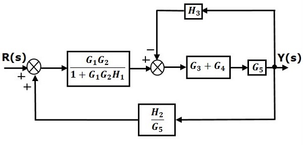
Single block diagram representation Figure 2. Block diagram rather than following typical reduction approach formula is given as below 3 SHORTCUT METHOD FOR BLOCK DIAGRAM REDUCTION TECHNIQUE TF If it is negative feedback system TF If it is positive feedback system But if there exist more than one forword path add forword path gain by considering it seperatelyAlso observe each. Ratio between transformation of output to the transformation of input when all the initial conditions are zero. First move the branch point of the path involving HI outside the loop involving H as shown in Figure 3-43a. Step 2 Repeat step 1 for remaining inputs.
 Source: youtube.com
Step 2 Repeat step 1 for remaining inputs. MATLAB allows solving of such blocks directly using some functions that is being discussed below with the help of the example. In this video i have explained Block Diagram Reduction rules with following timecodes. Components of Linear Time Invariant Systems LTIS. Block diagram Reduction method block diagram to SFG Control System-3 by SAHAV SINGH YADAV - YouTube.
 Source: electronicscoach.com
A block diagram consists of blocks that represent transfer functions of the different variables of interest. Block diagram rather than following typical reduction approach formula is given as below 3 SHORTCUT METHOD FOR BLOCK DIAGRAM REDUCTION TECHNIQUE TF If it is negative feedback system TF If it is positive feedback system But if there exist more than one forword path add forword path gain by considering it seperatelyAlso observe each. A very easy symbolic method for reduction of block diagrams or signal flow graphs with Matlab is presented. If a block diagram has many blocks not all of which are in cascade then it is useful to have rules for rearranging. The blocks connected in series parallel and as feedbacks are at times very tedious to compute.
 Source: pinterest.com
It helps to organize the variables and equations representing the control system. BLOCK DIAGRAM REDUCTION Block diagram is a pictorial representation of a control system showing inter-relation between the transfer function of various components. However in case of a complicated system the block diagram reduction technique becomes quite difficult as well as time-consuming. The block diagram reduction process takes more time for complicated systems. Block diagram Transfer Function.
 Source: sciencedirect.com
Block diagram rules. The method can be applied to every kind of diagram and it is possible to obtain in one stage all transfer functions for a given input. Figure 21 shows an element of the block diagram. However in case of a complicated system the block diagram reduction technique becomes quite difficult as well as time-consuming. Rules for reducing block diagram to find the transfer function About Press Copyright Contact us Creators Advertise Developers Terms Privacy Policy Safety How YouTube works Test new.
 Source: electrical4u.com
Step 3 Get the overall transfer function by adding all those transfer functions. Single block diagram representation Figure 2. Signal-Flow Graph Block diagram reduction is not convenient to a complicated system. A Block diagram of a dynamic system. 31 Signal-Flow Graph only utilize two.
 Source: mdpi.com
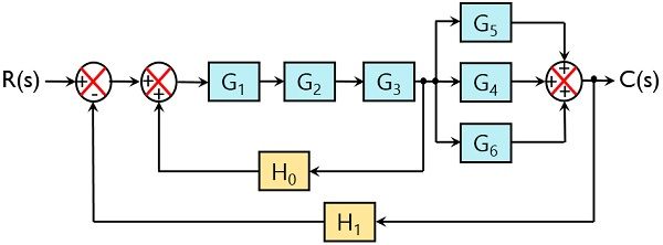
20 points Reduce the system shown in Figure 1 to a single transfer function using block diagram reduction method Ts CsRs. Here we are going to study block reduction using MATLAB. Single block diagram representation Figure 2. Because we have to draw the partially simplified. BLOCK DIAGRAM REDUCTION Block diagram is a pictorial representation of a control system showing inter-relation between the transfer function of various components.
 Source: electrical4u.com
Components of Linear Time Invariant Systems LTIS. We have seen that block diagram reduction was an efficient way of analyzing the system. A very easy symbolic method for reduction of block diagrams or signal flow graphs with Matlab is presented. For the successful implementation of this technique some rules for block diagram reduction to be followed. The blocks connected in series parallel and as feedbacks are at times very tedious to compute.
 Source: electronicscoach.com
Block diagram Reduction method block diagram to SFG Control System-3 by SAHAV SINGH YADAV - YouTube. Components of Linear Time Invariant Systems LTIS. Try to shift take off points towards right and Summing point towards left. Combining two blocks into one gives Figure 3-33c. 7a The current approach The proposed alternative approach Rules to be applied.
 Source: electrical4u.com
For the successful implementation of this technique some rules for block diagram reduction to be followed. Then eliminating two loops results in Figure 3-43b. The block diagram reduction process takes more time for complicated systems. Components of Linear Time Invariant Systems LTIS. Step 3 Get the overall transfer function by adding all those transfer functions.
 Source: tutorialspoint.com
The method can be applied to every kind of diagram and it is possible to obtain in one stage all transfer functions for a given input. Ratio between transformation of output to the transformation of input when all the initial conditions are zero. Signal-Flow graph is a very available approach to determine the relationship between the input and output variables of a sys- tem only needing a Masons formula without the complex reduc- tion procedures. 7a The current approach The proposed alternative approach Rules to be applied. Simplify the block diagram shown in Figure 3-13.
 Source: electronicscoach.com
Reduce the minor feedback loops. Reduce the blocks connected in series Step. 20 points Reduce the system shown in Figure 1 to a single transfer function using block diagram reduction method Ts CsRs. Because we have to draw the partially simplified. 31 Signal-Flow Graph only utilize two.
 Source: tutorialspoint.com
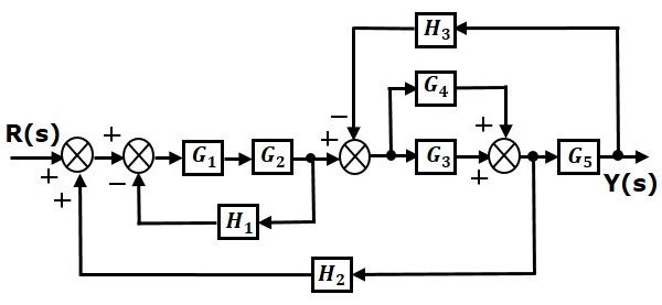
Lines with arrows that represent the actual. Then eliminating two loops results in Figure 3-43b. Signal-Flow Graph Block diagram reduction is not convenient to a complicated system. As with the block diagram the signal-ow graph oers a visual tool for graph. For the successful implementation of this technique some rules for block diagram reduction to be followed.
 Source: youtube.com
Block diagram Reduction method block diagram to SFG Control System-3 by SAHAV SINGH. Thus another method was proposed by S J Mason which is known as a signal flow graph. Boxes that represents the components of the system including their causality. Simplify the block diagram shown in Figure 3-42. This method helps to relate the input and.
This site is an open community for users to share their favorite wallpapers on the internet, all images or pictures in this website are for personal wallpaper use only, it is stricly prohibited to use this wallpaper for commercial purposes, if you are the author and find this image is shared without your permission, please kindly raise a DMCA report to Us.
If you find this site value, please support us by sharing this posts to your favorite social media accounts like Facebook, Instagram and so on or you can also bookmark this blog page with the title block diagram reduction method by using Ctrl + D for devices a laptop with a Windows operating system or Command + D for laptops with an Apple operating system. If you use a smartphone, you can also use the drawer menu of the browser you are using. Whether it’s a Windows, Mac, iOS or Android operating system, you will still be able to bookmark this website.