Bode diagram online
Home » Background » Bode diagram onlineYour Bode diagram online images are ready in this website. Bode diagram online are a topic that is being searched for and liked by netizens today. You can Download the Bode diagram online files here. Find and Download all free photos.
If you’re looking for bode diagram online images information connected with to the bode diagram online topic, you have visit the ideal site. Our website frequently gives you suggestions for seeing the maximum quality video and picture content, please kindly surf and find more informative video articles and images that match your interests.
Bode Diagram Online. Repose the equation in Bode plot form. Bode diagram Phase Group delay Nyquist diagram Pole zero Phase margin Oscillation analysis Upper and lower frequency limits. We can usually read the phase margin directly from the Bode plot as shown in the diagram above. Find more Engineering widgets in WolframAlpha.

For the transfer function given sketch the Bode log magnitude diagram which shows how the log magnitude of the system is affected by changing input frequency. This is done by calculating the vertical distance between the phase curve on the Bode phase plot and the x-axis at the frequency where the Bode magnitude plot 0 dB. The polezero diagram determines the gross structure of the transfer function. There is so much great material online please follow these links for excellent lectures and slides. This program takes as input a transfer function splits it into its constituent elements then draws the piecewise linear asymptotic. Magnitude Bode Plot Phase Bode Plot.
For the transfer function given sketch the Bode log magnitude diagram which shows how the log magnitude of the system is affected by changing input frequency.
It is important to understand how the locations of poles and zeros affect the shape of the graphs. It is commonly used in electrical engineering and control theory. It is the graphical representation of a linear time-invariant system transfer function. We can usually read the phase margin directly from the Bode plot as shown in the diagram above. Bode diagram Phase Group delay Nyquist diagram Pole zero Phase margin Oscillation analysis Upper and lower frequency limits. Ad Join Leading Researchers in the Field with Journal of Control Science and Engineering.

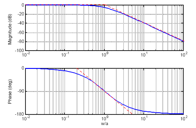
If sys is a multi-input multi-output MIMO model then bode produces an array of Bode plots each plot showing the. It is important to understand how the locations of poles and zeros affect the shape of the graphs. Bode diagrams are critical to understanding frequency-domain analysis and design of linear systems. Easy to plot bode diagram with real zeros and poles with our online bode plot generator. It is a graph used to compare the asymptotic bode plots with transfer function plots.

Repose the equation in Bode plot form. The polezero diagram determines the gross structure of the transfer function. If sys is a multi-input multi-output MIMO model then bode produces an array of Bode plots each plot showing the. We can usually read the phase margin directly from the Bode plot as shown in the diagram above. Bodesys creates a Bode plot of the frequency response of a dynamic system model sysThe plot displays the magnitude in dB and phase in degrees of the system response as a function of frequency.
 Source: la.mathworks.com
Sallen-Key Bessel 4th order. Ad Join Leading Researchers in the Field with Journal of Control Science and Engineering. Bodesys creates a Bode plot of the frequency response of a dynamic system model sysThe plot displays the magnitude in dB and phase in degrees of the system response as a function of frequency. Generate frequency response plots. Bode diagram Phase Group delay Nyquist diagram Pole zero Phase margin Oscillation analysis Upper and lower frequency limits.
 Source: controlsystemsacademy.com
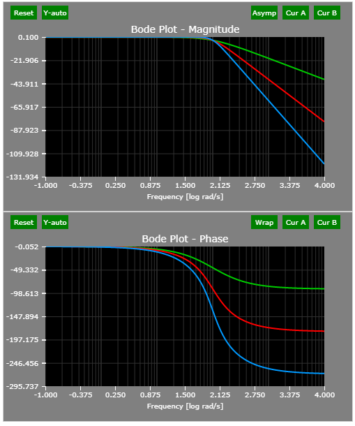
Repose the equation in Bode plot form. The pole at 30 radsec is the blue line. Get the free Diagrammes de Bode Nyquist Black widget for your website blog Wordpress Blogger or iGoogle. Bode Plot - 41. The phase is constant at 0 degrees.
 Source: researchgate.net
Of course we can easily program the transfer function into a computer to make such plots and for very complicated transfer functions this may be our only recourse. Uses of Bode Plot Diagram. Bode Plot Circuit 2. See the System Modeling with Transfer Functions article for more details. This is done in the diagram below.
 Source: engineers-excel.com
Submit Your Original Research Paper or Review on Control Systems and Applications. Nyquist plot of the transfer function s s-13 Bode plot of s 1-s sampling period 02. The polezero diagram determines the gross structure of the transfer function. It can be run online in the free hosting provider OnWorks for workstations. Generate frequency response plots.
 Source: engineers-excel.com
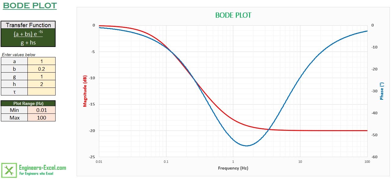
This program takes as input a transfer function splits it into its constituent elements then draws the piecewise linear asymptotic. The polezero diagram determines the gross structure of the transfer function. This is the Linux app named Bode diagram plotter whose latest release can be downloaded as BodeDiagramPlotter22betajar. Bode diagrams are critical to understanding frequency-domain analysis and design of linear systems. A Bode plot is a graph of the magnitude in dB or phase of the transfer function versus frequency.
 Source: lpsa.swarthmore.edu
A Bode plot is a graph of the magnitude in dB or phase of the transfer function versus frequency. It is the graphical representation of a linear time-invariant system transfer function. Bode diagram Phase Group delay Nyquist diagram Pole zero Phase margin Oscillation analysis Upper and lower frequency limits. Repose the equation in Bode plot form. Drawing piecewise linear asymptotic Bode diagrams by hand is difficult to learn.
 Source: anyflip.com
Drawing piecewise linear asymptotic Bode diagrams by hand is difficult to learn. Make use of this online bode diagram calculator to generate the Bode diagram by adding the Zeroes and Poles and changing the values. A Bode plot is a graph of the magnitude in dB or phase of the transfer function versus frequency. Get the free Diagrammes de Bode Nyquist Black widget for your website blog Wordpress Blogger or iGoogle. For the transfer function given sketch the Bode log magnitude diagram which shows how the log magnitude of the system is affected by changing input frequency.

Note that since the two poles are widely separated the gain will be very close to 103 60 dB over the frequency range 10 2to 105 rads. Easy to plot bode diagram with real zeros and poles with our online bode plot generator. These interactive tools are so good that learning. Magnitude Bode Plot Phase Bode Plot. For the transfer function given sketch the Bode log magnitude diagram which shows how the log magnitude of the system is affected by changing input frequency.
 Source: youtube.com
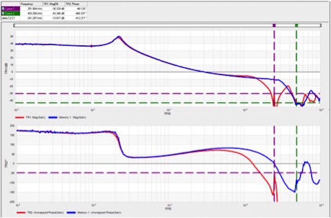
This is done by calculating the vertical distance between the phase curve on the Bode phase plot and the x-axis at the frequency where the Bode magnitude plot 0 dB. Use this online tool to easily build the bode plot complex graphs. Of course we can easily program the transfer function into a computer to make such plots and for very complicated transfer functions this may be our only recourse. If sys is a multi-input multi-output MIMO model then bode produces an array of Bode plots each plot showing the. Nyquist plot of the transfer function s s-13 Bode plot of s 1-s sampling period 02.
 Source: electrical4u.com
Ad Join Leading Researchers in the Field with Journal of Control Science and Engineering. 1 100 1 50 TF s recognized as 1 1 1 K TF s p with K 001 and p 1 50. F1 - f2 Hz frequency limits are optional Transient analysis Step response Impulse response Overshoot Final value of the step response. Get the free Diagrammes de Bode Nyquist Black widget for your website blog Wordpress Blogger or iGoogle. It is important to understand how the locations of poles and zeros affect the shape of the graphs.
 Source: researchgate.net
The pole at 30 radsec is the blue line. Repose the equation in Bode plot form. It is a graph used to compare the asymptotic bode plots with transfer function plots. This is done in the diagram below. The bode plot generator will show the real and asymptote plot for the magnitude and phase blot diagram.
 Source: engineers-excel.com
This point is known as the gain crossover frequency. F3 BodePlots F-5 Adding the four curves results in the asymptotic Bode diagram of the amplifier gain curve 5. Bode diagram Phase Group delay Nyquist diagram Pole zero Phase margin Oscillation analysis Upper and lower frequency limits. Bode automatically determines frequencies to plot based on system dynamics. 1 100 1 50 TF s recognized as 1 1 1 K TF s p with K 001 and p 1 50.
 Source: signalintegrityjournal.com
Bode Plot Circuit 2. Bode Plot Theory Transfer Function. Submit Your Original Research Paper or Review on Control Systems and Applications. Use this online tool to easily build the bode plot complex graphs. TFtransfer function 1 2100 TF s Step 1.
 Source: electronics-club.com
Note that since the two poles are widely separated the gain will be very close to 103 60 dB over the frequency range 10 2to 105 rads. The program BodePlotGui is a GUI graphical user interface tool written in the MATLAB programming language. The pole at 30 radsec is the blue line. Low Pass Filter Bode Plot -301dB magnitude There are currently no comments. Note that since the two poles are widely separated the gain will be very close to 103 60 dB over the frequency range 10 2to 105 rads.
 Source: lpsa.swarthmore.edu
Download and run online this app named Bode diagram plotter with OnWorks for free. Bode diagrams are a fundamental tool for understanding the frequency domain behavior of systems. Bode diagrams are critical to understanding frequency-domain analysis and design of linear systems. This is done in the diagram below. Ad Join Leading Researchers in the Field with Journal of Control Science and Engineering.
 Source: analog.com
Uses of Bode Plot Diagram. But in many cases the key features of the plot can be quickly sketched by. Easy to plot bode diagram with real zeros and poles with our online bode plot generator. It is important to understand how the locations of poles and zeros affect the shape of the graphs. This is done by calculating the vertical distance between the phase curve on the Bode phase plot and the x-axis at the frequency where the Bode magnitude plot 0 dB.
This site is an open community for users to do sharing their favorite wallpapers on the internet, all images or pictures in this website are for personal wallpaper use only, it is stricly prohibited to use this wallpaper for commercial purposes, if you are the author and find this image is shared without your permission, please kindly raise a DMCA report to Us.
If you find this site good, please support us by sharing this posts to your preference social media accounts like Facebook, Instagram and so on or you can also save this blog page with the title bode diagram online by using Ctrl + D for devices a laptop with a Windows operating system or Command + D for laptops with an Apple operating system. If you use a smartphone, you can also use the drawer menu of the browser you are using. Whether it’s a Windows, Mac, iOS or Android operating system, you will still be able to bookmark this website.