Circle diagram of induction motor pdf
Home » Background » Circle diagram of induction motor pdfYour Circle diagram of induction motor pdf images are ready in this website. Circle diagram of induction motor pdf are a topic that is being searched for and liked by netizens today. You can Find and Download the Circle diagram of induction motor pdf files here. Find and Download all royalty-free vectors.
If you’re searching for circle diagram of induction motor pdf pictures information connected with to the circle diagram of induction motor pdf topic, you have visit the right blog. Our site always gives you suggestions for seeing the highest quality video and image content, please kindly hunt and locate more enlightening video content and images that match your interests.
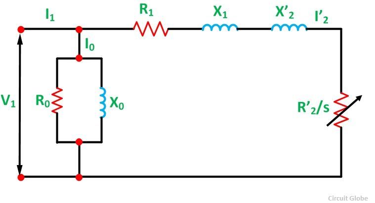
Circle Diagram Of Induction Motor Pdf. To Study and Measure Direct and Quadrature Axis Reactance of a 3 phase alternator by Slip Test 4. A circle diagram is commonly used to represent an induction motor. The construction of the circle diagram is based on the approximate equivalent circuit shown below. No load current and no load power factor.
 Diagram Circuit Diagram M In A Circle Hopinp Lampadineantizanzare It From hopinp.lampadineantizanzare.it
The concept of the Circle. Its stationary equivalent circuit. Circle diagram of an induction motor is graphical representation of ____________. The end of current vector for I1 is also seen to lie on another circle which is displaced from the dotted circle by an amount I0Its diameter is still VX01 and is parallel to the horizontal axis OC. Slip Ring Induction Motor draw its circle diagram 2. Circle diagram gives information about the equivalent circuit of the induction motor.
Draw the perpendicular bisector to AS to meet the horizontal line AB at C.
Short circuit current and short circuit power factor. The end of current vector for I1 is also seen to lie on another circle which is displaced from the dotted circle by an amount I0Its diameter is still VX01 and is parallel to the horizontal axis OC. Induction Motor Problems - Solutions Q 1 A 2-pole 3-phase induction motor fed by a 60 Hz source. Computation And Circle Diagrams GeneralCircle Diagram for a Series CircuitCircle Diagram of the Approximate Euuivalent CircleDctcrmination of GO and Rotor TestConstruction or the Circle QuantitiesStarting Of Induction Motors. A circle diagram is commonly used to represent an induction motor. Losses and efficiency Load test - No load and blocked rotor tests - Circle diagram Separation of no load losses Double cage rotors Induction generator Synchronous induction motor.
 Source: researchgate.net
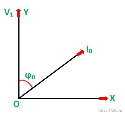
It provides information about the power output losses and the efficiency of the induction motor. Diagram was conceived in the late 19th century but is today no longer commonly utilized by. The concept of the Circle. Computations and Circle Diagrams 1315 B0 of the exciting circuit are assumed constant then I0 and φ0 are also constant. Computation And Circle Diagrams GeneralCircle Diagram for a Series CircuitCircle Diagram of the Approximate Euuivalent CircleDctcrmination of GO and Rotor TestConstruction or the Circle QuantitiesStarting Of Induction Motors.
 Source: electricaldeck.com
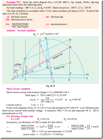
No load current and no load power factor. SAMPLE CALCULATION A sample calculation is reproduced here below for drawing a circle diagram of a three phase induction motor on the basis of which circle diagram for any rating of induction machine can be drawn - Example. Construction of Circle Diagram from designed data. Steinmetz provided the equivalent circuit we use today replacing the more complete Heyland circle diagram. Hence we find that if an induction motor is tested at various loads the.
 Source: electrical4u.com
Induction Motor Problems - Solutions Q 1 A 2-pole 3-phase induction motor fed by a 60 Hz source. Behrend and De La Tour published practical theory and the circle diagram in 1901. Hence we find that if an induction motor is tested at various loads the. The circle diagram can be drawn for alternators synchronous motors transformers induction motors. Steps to draw the circle diagram are See the figure on next.
 Source: circuitglobe.com
The concept of the Circle. A 460 -V 25-hp 60-Hz four-pole Y-connected wound-rotor induction motor has the following. I 2 at normal voltage I 2 V 1 V S Power factor under blocked-rotor condition with all quantities on per phase values is given as. Steps to draw the circle diagram are See the figure on next. Consider the diagram below.
 Source: machineryequipmentonline.com
Steinmetz provided the equivalent circuit we use today replacing the more complete Heyland circle diagram. Circuit Of an Induction MotorPower Balance EQuation Maximum Power OutputCorresponding Slip. No load current and no load power factor. Steinmetz provided the equivalent circuit we use today replacing the more complete Heyland circle diagram. Computations and Circle Diagrams 1315 B0 of the exciting circuit are assumed constant then I0 and φ0 are also constant.
 Source: electrical4u.com
The concept of the Circle. By 1911 Baileys book The induction Motor summarizes modern theory. Test on synchronous generator. Induction motor stator current from zero speed. Consider the diagram below.
 Source: circuitglobe.com
Its stationary equivalent circuit. A 460 -V 25-hp 60-Hz four-pole Y-connected wound-rotor induction motor has the following. A 400 V 40 hp 50 Hz 4 pole delta. Hence we find that if an induction motor is tested at various loads the. The Heyland diagram is an approximate representation of circle diagram applied to induction motors which assumes that stator input voltage rotor resistance and rotor reactance are constant and stator resistance and core loss are zero.
 Source: semanticscholar.org
I 2 at normal voltage I 2 V 1 V S Power factor under blocked-rotor condition with all quantities on per phase values is given as. The Circle Diagram of an Induction motor is very useful to study its performance under all operating conditions. Circle diagram of an induction motor. Draw the perpendicular bisector to AS to meet the horizontal line AB at C. Construction of Circle Diagram from designed data.
 Source: electrical4u.com
Computation And Circle Diagrams GeneralCircle Diagram for a Series CircuitCircle Diagram of the Approximate Euuivalent CircleDctcrmination of GO and Rotor TestConstruction or the Circle QuantitiesStarting Of Induction Motors. Circle diagram gives information about the equivalent circuit of the induction motor. Consider the diagram below. By 1911 Baileys book The induction Motor summarizes modern theory. In the Thevenin circuit the stator phase voltage has been replaced by its.
 Source: machineryequipmentonline.com
Steps to draw the circle diagram are See the figure on next. The circle diagram can be drawn for alternators synchronous motors transformers induction motors. From point S draw a vertical line SL to meet the line AB. Induction Motor Problems - Solutions Q 1 A 2-pole 3-phase induction motor fed by a 60 Hz source. Higher ac Suitable values of ac are ac10000 to 17500 Amp Condmeter up to 10 KW 20000 to 30000 Amp Condmeter up to 100 KW 30000 to 45000 Amp Condmeter 100 KW.

With C as centre draw a portion of circle passing through A and S. We should know following for drawing the circle diagram. Circuit Of an Induction MotorPower Balance EQuation Maximum Power OutputCorresponding Slip. Short circuit current and short circuit power factor. Computation And Circle Diagrams GeneralCircle Diagram for a Series CircuitCircle Diagram of the Approximate Euuivalent CircleDctcrmination of GO and Rotor TestConstruction or the Circle QuantitiesStarting Of Induction Motors.
 Source: machineryequipmentonline.com
It is the diagrammatic representation of the performance of the induction motor. It is the diagrammatic representation of the performance of the induction motor. Construction of Circle Diagram from designed data. Induction Motor Problems - Solutions Q 1 A 2-pole 3-phase induction motor fed by a 60 Hz source. Circuit Of an Induction MotorPower Balance EQuation Maximum Power OutputCorresponding Slip.
 Source: circuitglobe.com
The Heyland diagram is an approximate representation of circle diagram applied to induction motors which assumes that stator input voltage rotor resistance and rotor reactance are constant and stator resistance and core loss are zero. It provides information about the power output losses and the efficiency of the induction motor. Short circuit current and short circuit power factor. With C as centre draw a portion of circle passing through A and S. Isc is more Dia of circle diagram Overload Capacity 4.
 Source: electricaldeck.com
View Homework Help - Induction Motor Solutionspdf from EE 4701 at University of Minnesota Morris. It provides information about the power output losses and the efficiency of the induction motor. It is the diagrammatic representation of the performance of the induction motor. Diagram was conceived in the late 19th century but is today no longer commonly utilized by. We cannot determine the.
 Source: researchgate.net
Diagram was conceived in the late 19th century but is today no longer commonly utilized by. To perform no load and blocked rotor test on a machines and to determine the parameters of its. Isc is more Dia of circle diagram Overload Capacity 4. The no-load current and the no load angle calculated from no load test is plotted. What is circle diagram of induction motor Please scroll down to see the correct answer and solution guideRight Answer is.
 Source: hopinp.lampadineantizanzare.it
It is the diagrammatic representation of the performance of the induction motor. Phase angle for no-load condition 0 0 0 0 3 V I P Φ Blocked Rotor Test. Losses and efficiency Load test - No load and blocked rotor tests - Circle diagram Separation of no load losses Double cage rotors Induction generator Synchronous induction motor. Construction of Circle Diagram from designed data. Simply a graphical representation of the locus of.
 Source: brainkart.com
Slip Ring Induction Motor draw its circle diagram 2. Cos S W S V S I S With the same current scale I 2. Types Construction and principle of operation 3 phase Induction Motor general phasor diagram equivalent circuit power and torque relations condition for maximum torque circle diagram Performance characteristics effect of rotor resistance on speed torque characteristics stable unstable region of. Computations and Circle Diagrams 1315 B0 of the exciting circuit are assumed constant then I0 and φ0 are also constant. Phase angle for no-load condition 0 0 0 0 3 V I P Φ Blocked Rotor Test.
 Source: researchgate.net
It provides information about the power output losses and the efficiency of the induction motor. It provides information about the power output losses and the efficiency of the induction motor. Three Phase Induction Motors. Simply a graphical representation of the locus of. The circle diagram can be drawn for alternators synchronous motors transformers induction motors.
This site is an open community for users to submit their favorite wallpapers on the internet, all images or pictures in this website are for personal wallpaper use only, it is stricly prohibited to use this wallpaper for commercial purposes, if you are the author and find this image is shared without your permission, please kindly raise a DMCA report to Us.
If you find this site beneficial, please support us by sharing this posts to your preference social media accounts like Facebook, Instagram and so on or you can also save this blog page with the title circle diagram of induction motor pdf by using Ctrl + D for devices a laptop with a Windows operating system or Command + D for laptops with an Apple operating system. If you use a smartphone, you can also use the drawer menu of the browser you are using. Whether it’s a Windows, Mac, iOS or Android operating system, you will still be able to bookmark this website.