Cisco ucs cabling diagram
Home » Background » Cisco ucs cabling diagramYour Cisco ucs cabling diagram images are available in this site. Cisco ucs cabling diagram are a topic that is being searched for and liked by netizens now. You can Download the Cisco ucs cabling diagram files here. Download all royalty-free images.
If you’re searching for cisco ucs cabling diagram pictures information connected with to the cisco ucs cabling diagram interest, you have visit the ideal site. Our website frequently provides you with suggestions for seeking the maximum quality video and image content, please kindly surf and locate more enlightening video articles and images that match your interests.
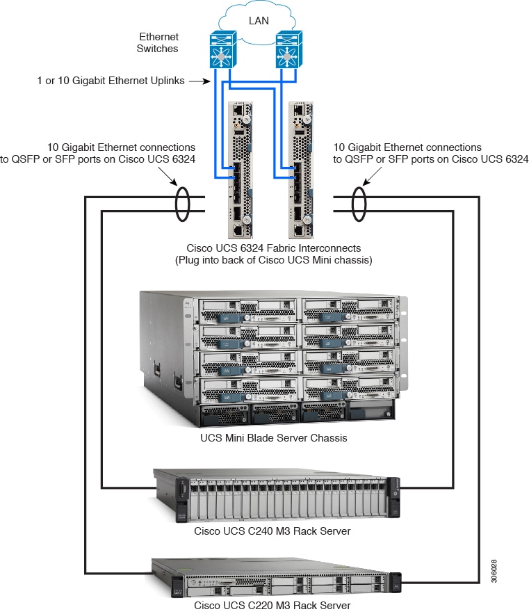
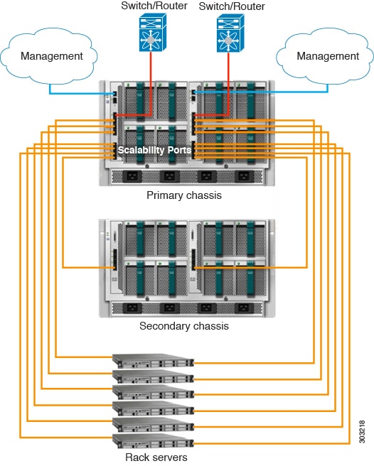
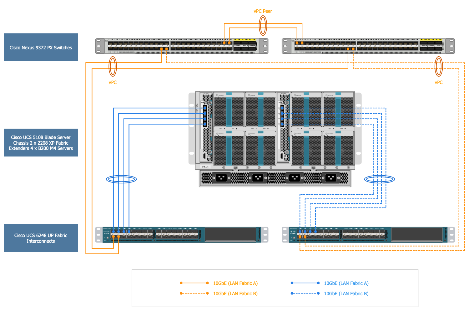
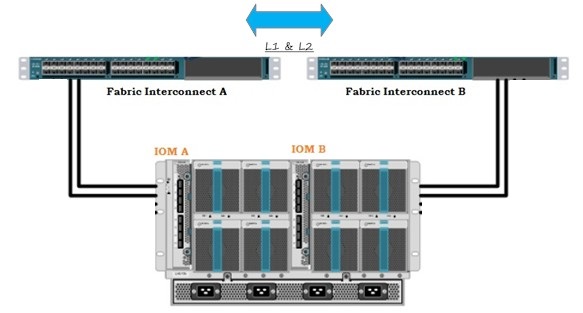
Cisco Ucs Cabling Diagram. Connects UCS blade chassis to the Fabric Interconnect Four 10 Gigabit Ethernet FCoE capable SFP ports Up to 2 Fabric Extenders per chassis for redundancy and up to 80. Cisco UCS Ethernet Frame Flows. On the San Switch side our Storage guy configured SW1 as vlan10 and SW2 as vlan20. Cisco OEM 19 Server Rack is housing the UCS equipment.
 Ucs Good Practices Nerdknobs From nerdknobs.net
We have found it to be easier to understand compared to the existing diagrams in the training materials. Note that Uplink Ports are also known as border links. My question pertains to the correct cabling vSAN setup from the UCS FI to the San Switch Cisco MDS. I wanted to post this as a general guideline for those new to UCS who may be setting up their first lab or production environments. Plastic blanking panels black to restrict cold air leaking to the hot aisle. At least that is how the screen is worded.
FI1 port 25 - SW1 port 3.
The Cisco Nexus configuration makes sure that Ethernet traffic flows are optimized for the Epic application. Cisco UCS Manager typically is deployed in a clustered active-passive configuration on redundant fabric. Cisco UCS and Cisco Services andor Partner services can help your organization. Power on this Fabric Interconnect leaving the secondary Interconnect powered off for now. Contents vi Cisco UCS C220 M4 Server Installation and Service Guide OL-32473-01 RAID Controller Cabling C-7 Cable Routing C-7 Cisco UCS C220 M4 Server Cabling C-8 SFF 8-Drive Backplane Cabling C-8 LFF 4-Drive Backplane Cabling C-9 Embedded SATA RAID Controllers C-10 Embedded SATA RAID Controller Requirements C-10 Embedded SATA RAID. Fewer cables network interface cards host bus adapters ports and switches.
 Source: blog.purestorage.com
Network diagram topology commonly designed within connected nodes. Introduction to Cisco UCS Architecture. Also you must compete the cabling requirements as described in the Cabling Diagram section. In the Navigation pane click the Equipment tab. Cabling Considerations for Fabric Port Channels When you configure the links between the Cisco UCS 2200 Series FEX and a Cisco UCS 6200 series fabric interconnect in fabric port channel mode the available virtual interface namespace VIF on the adapter varies depending on where the FEX uplinks are connected to the fabric interconnect ports.
 Source: veducate.co.uk
The Cisco Nexus configuration makes sure that Ethernet traffic flows are optimized for the Epic application. Cisco UCS Manager typically is deployed in a clustered active-passive configuration on redundant fabric. The Cisco Nexus configuration makes sure that Ethernet traffic flows are optimized for the Epic application. The Cisco UCS 6200 Series interconnects support out-of-band management through a dedicated 101001000-Mbps Ethernet management port as well as in-band management. We have found it to be easier to understand compared to the existing diagrams in the training materials.
 Source: sysadmintutorials.com
AR7710 Cisco UCS 5108 Chassis 600 mm Chassis hot swap component access Cisco UCS 5108 Chassis. Its important to note that UCS is highly customizable and that configuration settings will be different between environments. The cables should be connected as described in the section Cabling Diagram. For the Nimble each controller should have one connection to each FI. What I also realized is that with all.
 Source: cisco.com
The Cisco UCS B200 M5 Blade Servers are installed in the Cisco UCS 5108 AC blade chassis. Perform these procedures after the Cisco UCS B200 M5 Blade Servers are installed in the Cisco UCS 5108 AC blade chassis. On the San Switch side our Storage guy configured SW1 as vlan10 and SW2 as vlan20. Fewer cables network interface cards host bus adapters ports and switches. What I also realized is that with all.
 Source: conceptdraw.com
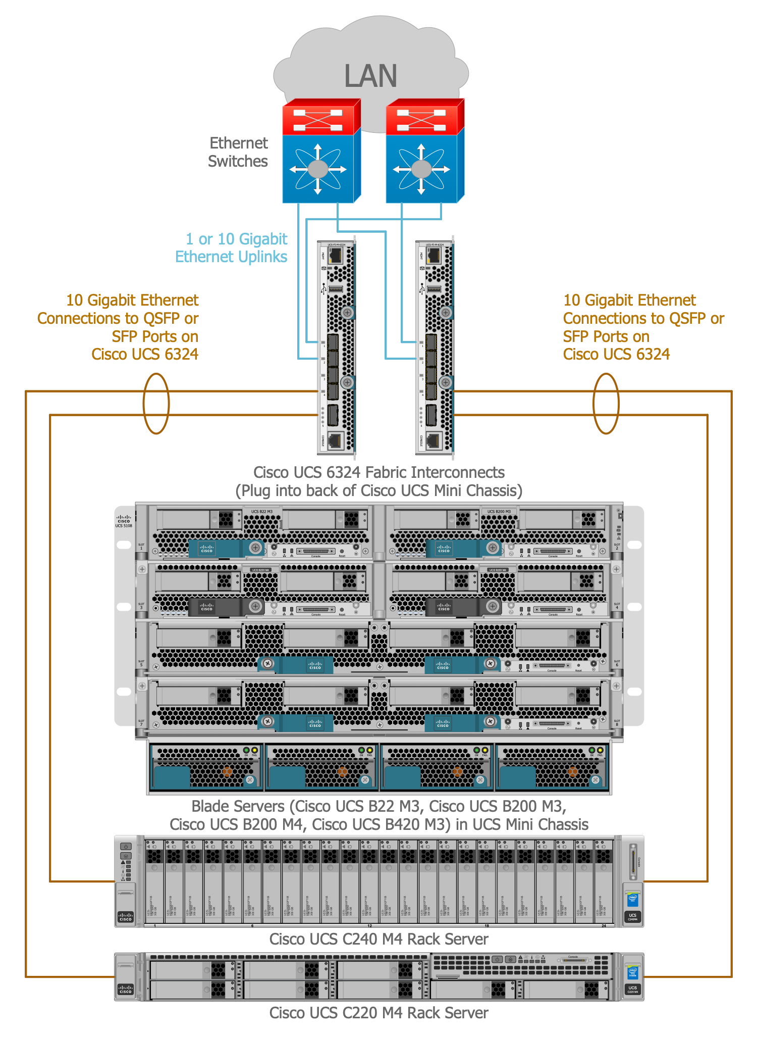
Cisco Network Topology is the arrangement of the Cisco symbols that display scheme of computer network. In the Navigation pane click the Equipment tab. Any Cisco equipment on the network are named like node. The Cisco Network Diagrams solution uses Cisco network symbols and Cisco icons to visualize computer networks. Cisco UCS 2304 Fabric Extender is not supported.
 Source: cisco.com
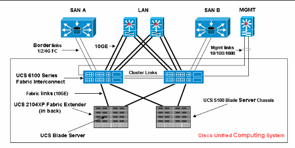
This is a typical topology used with the Cisco UCS. Its important to note that UCS is highly customizable and that configuration settings will be different between environments. To set up the Cisco UCS compute platform complete the following procedures. Note that Uplink Ports are also known as border links. Here is a diagram of the Cisco UCS 5454 Fabric Interconnect with an expiation of what each port does.
 Source: docs.netapp.com
I wanted to post this as a general guideline for those new to UCS who may be setting up their first lab or production environments. When you configure a Cisco UCS system you tell the system how many cables the Fabric Interconnects should use to discover each chassis. Cisco UCS Manager typically is deployed in a clustered active-passive configuration on redundant fabric. AR7710 Cisco UCS 5108 Chassis 600 mm Chassis hot swap component access Cisco UCS 5108 Chassis. As you can see the C125 M5 wins out in the density areas but if minimal cabling is a priority then Blades are a great option or the S3260 servers for maximum storage.
 Source: vadmin-land.azurewebsites.net
Configure Uplink Ethernet Ports. My question pertains to the correct cabling vSAN setup from the UCS FI to the San Switch Cisco MDS. Installation for Cisco UCS Manager Integration. Attached is a redrawn UCS connectivity diagram which summaries the internal works of the UCS components in particular the chassis and blades. Hopefully this information will help you better understand UCS networking.
 Source: cisco.com
Fewer cables network interface cards host bus adapters ports and switches. A quick diagram to show how the devices were all connected up the connections between the FI and the Chassis are coloured differently to define the overlapping cables in the diagram and do not indicate any special separate configuration. I started working with the Cisco Unified Computing System more commonly known as Cisco UCS very soon after its initial release. Fewer cables network interface cards host bus adapters ports and switches. Connects UCS blade chassis to the Fabric Interconnect Four 10 Gigabit Ethernet FCoE capable SFP ports Up to 2 Fabric Extenders per chassis for redundancy and up to 80.
 Source: subscription.packtpub.com
The Cisco UCS B200 M5 Blade Servers are installed in the Cisco UCS 5108 AC blade chassis. The Cisco Network Diagrams solution uses Cisco network symbols and Cisco icons to visualize computer networks. FI2 port 26 - SW2 port 4. Attached is a redrawn UCS connectivity diagram which summaries the internal works of the UCS components in particular the chassis and blades. Any Cisco equipment on the network are named like node.
 Source: subscription.packtpub.com
While some earlier models were larger Im looking at you Cisco UCS 6296 the Cisco UCS 6454 Fabric Interconnect is a 1 U Rack Mount device and honestly it looks like any other network switch. Note that Uplink Ports are also known as border links. FI2 port 25 - SW1 port 4. FI1 port 25 - SW1 port 3. To set up the Cisco UCS compute platform complete the following procedures.

UCS Connectivity Diagram. Cabling Considerations for Fabric Port Channels When you configure the links between the Cisco UCS 2200 Series FEX and a Cisco UCS 6200 series fabric interconnect in fabric port channel mode the available virtual interface namespace VIF on the adapter varies depending on where the FEX uplinks are connected to the fabric interconnect ports. Fewer cables network interface cards host bus adapters ports and switches. AR7710 Cisco UCS 5108 Chassis 600 mm Chassis hot swap component access Cisco UCS 5108 Chassis. Attached is a redrawn UCS connectivity diagram which summaries the internal works of the UCS components in particular the chassis and blades.
 Source: blog.purestorage.com
Cisco OEM 19 Server Rack is housing the UCS equipment. Perform these procedures after the Cisco UCS B200 M5 Blade Servers are installed in the Cisco UCS 5108 AC blade chassis. Recommended cable managers. The possibility to create a Cisco UCS connectivity diagram is delivered with Cisco Networking solution that provides 13 libraries containing 609 vector objects of standardized Cisco devices and equipment such as Cisco servers Cisco switches Cisco Fabric Interconnects etc. Installation for Cisco UCS Manager Integration.
 Source: koolaid.info
Upgrading to Cisco UCS S3260. Cisco Nexus switch configuration. Cisco OEM 19 Server Rack is housing the UCS equipment. As you can see the C125 M5 wins out in the density areas but if minimal cabling is a priority then Blades are a great option or the S3260 servers for maximum storage. Following on from cabling our Cisco UCS infrastructure we will first begin to configure the Fabric Interconnects using the Basic System Configuration Dialog.
 Source: conceptdraw.com
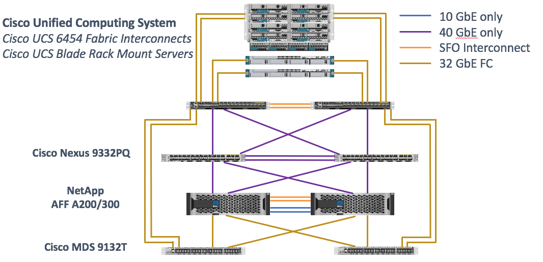
Installation for Cisco UCS Manager Integration. FI2 port 26 - SW2 port 4. Hopefully this information will help you better understand UCS networking. Any Cisco equipment on the network are named like node. The Cisco MDS 9100 Series FC switches provide redundant 16Gb FC connectivity between the NetApp AFF A700 controllers and the Cisco UCS compute fabric.
 Source: unixarena.com
A fault-tolerant pair of Cisco Nexus 9300 Series Ethernet switches is deployed for the solution. At least that is how the screen is worded. When you configure a Cisco UCS system you tell the system how many cables the Fabric Interconnects should use to discover each chassis. A quick diagram to show how the devices were all connected up the connections between the FI and the Chassis are coloured differently to define the overlapping cables in the diagram and do not indicate any special separate configuration. For the Nimble each controller should have one connection to each FI.
 Source: slidetodoc.com
Log into Cisco UCS Manager. Also you must compete the cabling requirements as described in the Cabling Diagram section. Installation for Cisco UCS Manager Integration. The cables should be connected as described in the section Cabling Diagram. Cisco Network Topology is the arrangement of the Cisco symbols that display scheme of computer network.
 Source: nerdknobs.net
Example Cisco UCS Front View from the COLD AISLE. AR7710 Cisco UCS 5108 Chassis 600 mm Chassis hot swap component access Cisco UCS 5108 Chassis. Cisco UCS Cabling Plan Front. Installation for Cisco UCS Manager Integration. While some earlier models were larger Im looking at you Cisco UCS 6296 the Cisco UCS 6454 Fabric Interconnect is a 1 U Rack Mount device and honestly it looks like any other network switch.
This site is an open community for users to share their favorite wallpapers on the internet, all images or pictures in this website are for personal wallpaper use only, it is stricly prohibited to use this wallpaper for commercial purposes, if you are the author and find this image is shared without your permission, please kindly raise a DMCA report to Us.
If you find this site convienient, please support us by sharing this posts to your own social media accounts like Facebook, Instagram and so on or you can also bookmark this blog page with the title cisco ucs cabling diagram by using Ctrl + D for devices a laptop with a Windows operating system or Command + D for laptops with an Apple operating system. If you use a smartphone, you can also use the drawer menu of the browser you are using. Whether it’s a Windows, Mac, iOS or Android operating system, you will still be able to bookmark this website.