Cobalt particle diagram
Home » Wallpapers » Cobalt particle diagramYour Cobalt particle diagram images are available. Cobalt particle diagram are a topic that is being searched for and liked by netizens today. You can Get the Cobalt particle diagram files here. Find and Download all free photos.
If you’re looking for cobalt particle diagram pictures information linked to the cobalt particle diagram keyword, you have pay a visit to the right blog. Our website always provides you with hints for seeking the maximum quality video and picture content, please kindly search and locate more enlightening video content and graphics that match your interests.
Cobalt Particle Diagram. Schematic diagram and wt of material used for preparation of isotropic and anisotropic MRE. B Gamma radiation from cobalt-60 can be used to destroy tumours. Schematic diagram of magnetorheological elastomer MRE preparation. Compound Elements Weight g wt Silicon Rubber 47 47 Cobalt Powder 53 53 Figure 1.
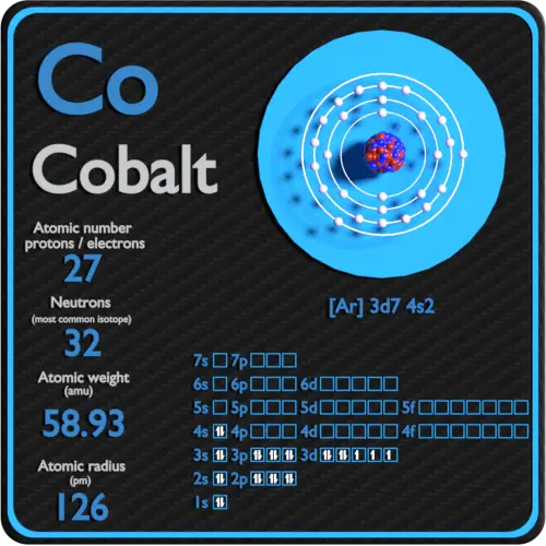
 Cobalt Protons Neutrons Electrons Electron Configuration From material-properties.org
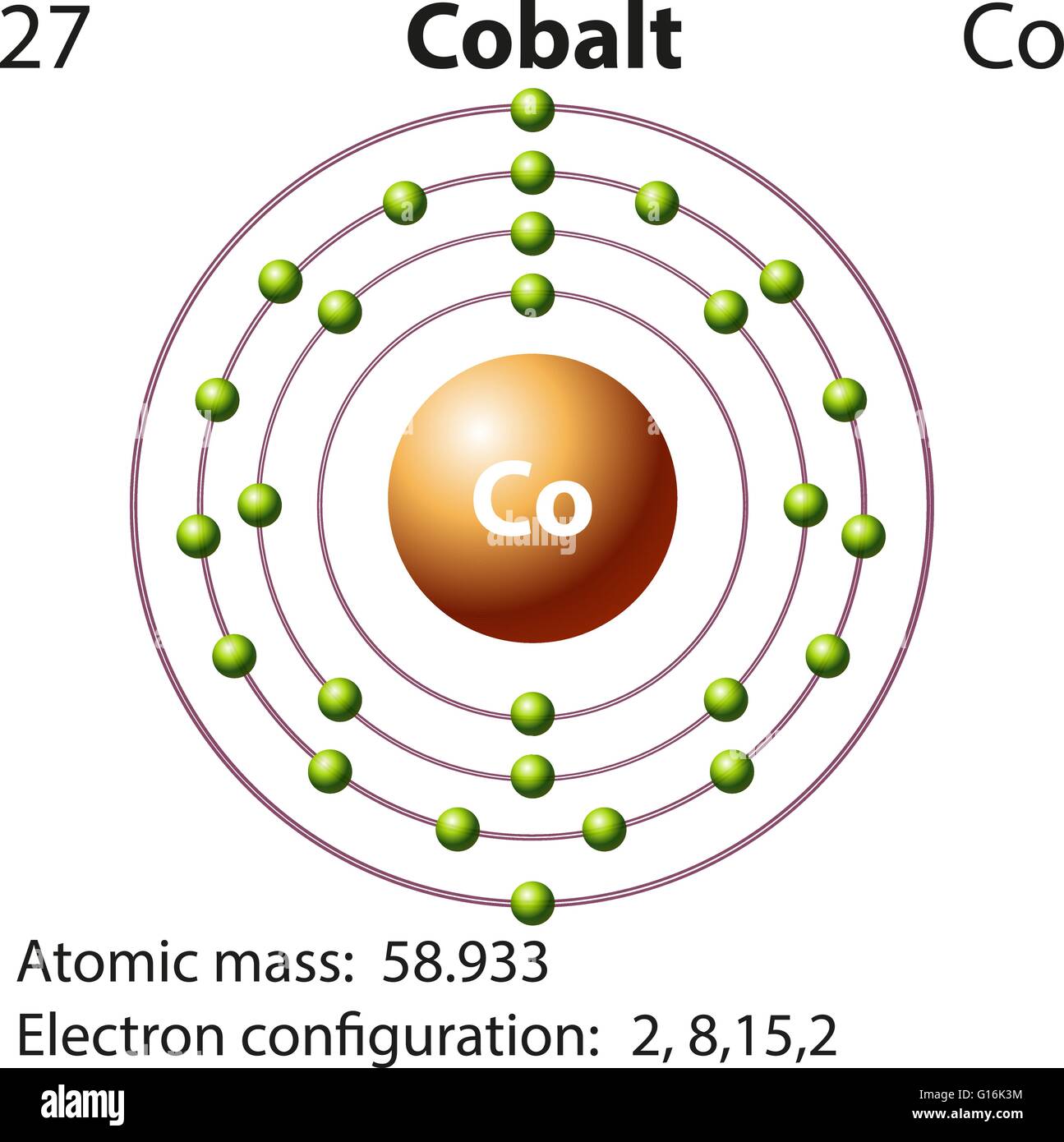
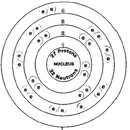
Cobalt is an important gamma-ray source which is used as a radio therapeutic agent for cancer treatment Baskar Lee Yeo Yeoh 2012. This is demonstrated by the diagrams calculated for cobalt with particle sizes I 10 O0 and lOO0m. It is produced artificially in nuclear reactors. The material constants used are listed in Table I. The electron shells are shown moving outward from the nucleus. The first phase likely representing mucociliary clearance of particles deposited in the tracheobronchial region has a half-time on the order of 2-44 hours.
The amount we need is very small and the body contains only about 1 milligram.
An example of how cobalt can precipitate in a fluid melt glaze at cone 6. I Complete the sentence by putting a cross in the box next to your answer. Deliberate industrial production depends on neutron activation of bulk samples of the monoisotopic and mononuclidic cobalt isotope 59 Co. The energy diagram of stationary magnetization states existing in polycrystalline cobalt nanoparticles in the range of diameters 20 D 60 nm has been calculated by means of numerical simulation. The diagram in Fig. The electron shells are shown moving outward from the nucleus.
 Source: alamy.com
For example cobalt-60 an isotope that emits gamma rays used to treat cancer has a half-life of 527 years Figure 35. The first phase likely representing mucociliary clearance of particles deposited in the tracheobronchial region has a half-time on the order of 2-44 hours. Left is the raw powder plastic-formed into a sample with 2 veegum. 157 - Green Particles Transparent. The symbols indicate the phases of cobalt as determined by means of in situ x-ray diffraction at high pressure and temperature.
 Source: researchgate.net
Cobalt carbonate top and copper carbonate bottom. G of cobaltII carbonate were added to 40 cm 3 of hydrochloric acid concentration 20 mol dm 3. HUMAN EXPOSURE AND TOXICITY. From the thermodynamic analysis one can assume that the lithium in LiCoO 2 ionises with the rest of the ions in the LiCl-KCl melt as per Eq. I Complete the sentence by putting a cross in the box next to your answer.
 Source: researchgate.net
Cobalt is an important gamma-ray source which is used as a radio therapeutic agent for cancer treatment Baskar Lee Yeo Yeoh 2012. ε -Co open circles and. Particles By Fundamental Interactions - Elementary Particle Venn Diagram. Schematic diagram and wt of material used for preparation of isotropic and anisotropic MRE. The dotted line represents the transition from stage I and II - III as defined by Thnmler and Thonlma 15.

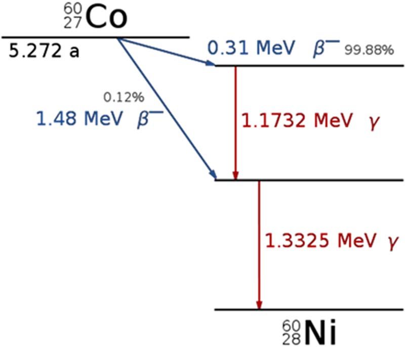
In a given cobalt-60 source since half of the nuclei decay every 527 years both the amount of material and the intensity of the radiation emitted is cut in half every 527 years. Particles By Fundamental Interactions - Elementary Particle Venn Diagram. CoCO3 2HCl CoCl2 CO2 H2O CoCl2 6H2O CoCl26H2O maximum yield. 89 gcm 3 Color. Compound Elements Weight g wt Silicon Rubber 47 47 Cobalt Powder 53 53 Figure 1.
 Source: researchgate.net
ATOMIC PER CENT COBALT Fig. Radioactive cobalt-60 is used to treat cancer and in some countries to irradiate food to preserve it. Schematic diagram of magnetorheological elastomer MRE preparation. Component of cobalt-based magnetorheological elastomer MRE. Deliberate industrial production depends on neutron activation of bulk samples of the monoisotopic and mononuclidic cobalt isotope 59 Co.
 Source: researchgate.net
Component of cobalt-based magnetorheological elastomer MRE. Deliberate industrial production depends on neutron activation of bulk samples of the monoisotopic and mononuclidic cobalt isotope 59 Co. In the early stages of the process considerable stresses are caused by platelets of the tetragonal phase which lie. Measurable quantities are also produced as a by-product of typical nuclear power plant. In a given cobalt-60 source since half of the nuclei decay every 527 years both the amount of material and the intensity of the radiation emitted is cut in half every 527 years.
 Source: researchgate.net
The material constants used are listed in Table I. Note that for a given substance the intensity of radiation that it produces is directly. The phase diagram of cobalt. Cobalt is an important gamma-ray source which is used as a radio therapeutic agent for cancer treatment Baskar Lee Yeo Yeoh 2012. An example of how cobalt can precipitate in a fluid melt glaze at cone 6.

CoCO3 2HCl CoCl2 CO2 H2O CoCl2 6H2O CoCl26H2O maximum yield. Left is the raw powder plastic-formed into a sample with 2 veegum. Measurable quantities are also produced as a by-product of typical nuclear power plant. 3 indicates the stability for different cobalt oxides IIIII and cobalt metal at 500 C. B Gamma radiation from cobalt-60 can be used to destroy tumours.
 Source: researchgate.net
It is long past the fuming stage. Schematic diagram of magnetorheological elastomer MRE preparation. Particles emitted during cobalt mining consists radioactive emissions cancer-causing particles and particles which may cause vision problems vomiting and nausea heart problems and Thyroid damage. The CuCO 3 is quickly densifying over the past 100 degrees and should begin to melt soon. 28700 C 314315 K 51980 F Number of ProtonsElectrons.

14950 C 176815 K 27230 F Boiling Point. Compound Elements Weight g wt Silicon Rubber 47 47 Cobalt Powder 53 53 Figure 1. ε -Co open circles and. CoCO3 2HCl CoCl2 CO2 H2O CoCl2 6H2O CoCl26H2O maximum yield. Particles emitted during cobalt mining consists radioactive emissions cancer-causing particles and particles which may cause vision problems vomiting and nausea heart problems and Thyroid damage.
 Source: researchgate.net
Four fatal cases of diffuse interstitial lung-fibrosis have been described among workers who had been exposed to high concentration of cobalt carbonate 04 up to 5-10 mg Cocu m in a cobalt catalyst plant during the 1930s and 1940s. Gamma radiation is used because 1 A gamma can penetrate further than alpha or beta B gamma is more ionising than alpha or beta. Calculate the maximum yield of cobaltII chloride-6-water and show that the cobaltII carbonate was in excess. The diagram in Fig. The third clearance phase representing tong-term clearance from the.
 Source: researchgate.net
1 Equilibrium diagram of the cobalt-platinum system that the aoo directions of the ordered particles are parallel with the corresponding axes in the parent lattice. Four fatal cases of diffuse interstitial lung-fibrosis have been described among workers who had been exposed to high concentration of cobalt carbonate 04 up to 5-10 mg Cocu m in a cobalt catalyst plant during the 1930s and 1940s. CoCO3 2HCl CoCl2 CO2 H2O CoCl2 6H2O CoCl26H2O maximum yield. ε -Co open circles and. HUMAN EXPOSURE AND TOXICITY.
 Source: researchgate.net
Measurable quantities are also produced as a by-product of typical nuclear power plant. Schematic diagram of magnetorheological elastomer MRE preparation. For example cobalt-60 an isotope that emits gamma rays used to treat cancer has a half-life of 527 years Figure 35. Compound Elements Weight g wt Silicon Rubber 47 47 Cobalt Powder 53 53 Figure 1. Schematic diagram and wt of material used for preparation of isotropic and anisotropic MRE.
 Source: researchgate.net
27 Number of Neutrons. Four fatal cases of diffuse interstitial lung-fibrosis have been described among workers who had been exposed to high concentration of cobalt carbonate 04 up to 5-10 mg Cocu m in a cobalt catalyst plant during the 1930s and 1940s. Schematic diagram and wt of material used for preparation of isotropic and anisotropic MRE. The dotted line represents the transition from stage I and II - III as defined by Thnmler and Thonlma 15. Measurable quantities are also produced as a by-product of typical nuclear power plant.
 Source: researchgate.net
Particles By Fundamental Interactions - Elementary Particle Venn Diagram. 589332 amu Melting Point. Compound Elements Weight g wt Silicon Rubber 47 47 Cobalt Powder 53 53 Figure 1. Cobalt is an important gamma-ray source which is used as a radio therapeutic agent for cancer treatment Baskar Lee Yeo Yeoh 2012. 28700 C 314315 K 51980 F Number of ProtonsElectrons.
 Source: material-properties.org
In the early stages of the process considerable stresses are caused by platelets of the tetragonal phase which lie. The material constants used are listed in Table I. The first phase likely representing mucociliary clearance of particles deposited in the tracheobronchial region has a half-time on the order of 2-44 hours. Nishizawa Calculation of Phase Diagrams of the Iron-Copper and Cobalt-Copper SystemsCalphad 4 83 1980. In a given cobalt-60 source since half of the nuclei decay every 527 years both the amount of material and the intensity of the radiation emitted is cut in half every 527 years.
 Source: chemistryexplained.com
Health exams of other workers who had been working in the plant before 1940 revealed a very high prevalence. Schematic diagram of magnetorheological elastomer MRE preparation. Nishizawa Calculation of Phase Diagrams of the Iron-Copper and Cobalt-Copper SystemsCalphad 4 83 1980. The third clearance phase representing tong-term clearance from the. CoCO3 2HCl CoCl2 CO2 H2O CoCl2 6H2O CoCl26H2O maximum yield.
 Source: researchgate.net
Indicates presence of a phase diagram Article Google Scholar. For example cobalt-60 an isotope that emits gamma rays used to treat cancer has a half-life of 527 years Figure 35. G of cobaltII carbonate were added to 40 cm 3 of hydrochloric acid concentration 20 mol dm 3. The symbols indicate the phases of cobalt as determined by means of in situ x-ray diffraction at high pressure and temperature. CoCO3 2HCl CoCl2 CO2 H2O CoCl2 6H2O CoCl26H2O maximum yield.
This site is an open community for users to do submittion their favorite wallpapers on the internet, all images or pictures in this website are for personal wallpaper use only, it is stricly prohibited to use this wallpaper for commercial purposes, if you are the author and find this image is shared without your permission, please kindly raise a DMCA report to Us.
If you find this site value, please support us by sharing this posts to your preference social media accounts like Facebook, Instagram and so on or you can also save this blog page with the title cobalt particle diagram by using Ctrl + D for devices a laptop with a Windows operating system or Command + D for laptops with an Apple operating system. If you use a smartphone, you can also use the drawer menu of the browser you are using. Whether it’s a Windows, Mac, iOS or Android operating system, you will still be able to bookmark this website.