Dma timing diagram
Home » Background » Dma timing diagramYour Dma timing diagram images are available in this site. Dma timing diagram are a topic that is being searched for and liked by netizens now. You can Download the Dma timing diagram files here. Download all free vectors.
If you’re searching for dma timing diagram images information linked to the dma timing diagram topic, you have visit the right site. Our website always provides you with hints for seeking the highest quality video and picture content, please kindly search and find more informative video articles and graphics that match your interests.
Dma Timing Diagram. One could call HOLD input a DMA request input and HLDA output a DMA grant signal. DMA stands for Direct Memory Access. Two 16-bit registers are internally associated with each channel These registers. 2 Exception An exception is any condition that needs.
 Timing Of Dma Transfers Download Scientific Diagram From researchgate.net
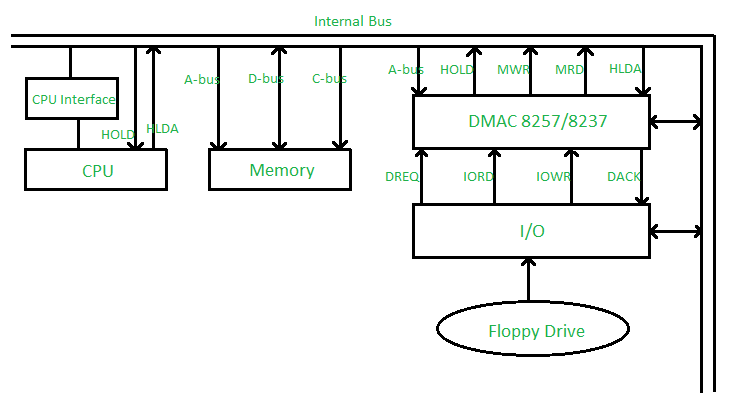
Direct Memory Access DMA 8257 Basics Block Diagram Working Operation Watch later. A timing device such that after preset time interval is set an event must occur during. Lets illustrate the CoCo12Dragon timing diagram. The following image shows the pin diagram of a 8257 DMA controller. It also shows the interface with the 8085 using a 3-to-8 decoder 8237 has four independent channels CH0-CH3. The first is a 16 bit standard IO read.
DMA Timing REF DESCRIPTION DRIVER RECEIVER MIN MAX MIN MAX 1 MEMR pulse width 214 203 2 SA setup to MEMR 81 70 3 SA hold from MEMR 36 25 4 IOCHRDY deasserted from MEMR 81 159 5 MEMR deasserted from IOCHRDY 125 125 6 REFRESH setup to MEMR 125 114 7 REFRESH hold from MEMR Note 1 31 250 20 239.
Shown here the address and data lines are activated by the DMA engine during the entire computer cycle along with the enabled RW line. Shown here the address and data lines are activated by the DMA engine during the entire computer cycle along with the enabled RW line. A timing device such that after preset time interval is set an event must occur during. DMA stands for Direct Memory Access and is a method of transferring data from the computers RAM to another part of the computer without processing it using the CPU. Timing diagram of input capture. Using cycle stealing data is transferred 1 byte at a time.

Nowadays DMA can transfer data as fast as 60 M byte per. DMA controller is a control unit part of IO devices interface circuit which can transfer blocks of data between IO devices and main memory with minimal intervention from the processor. Draw a timing diagram that shows a complete DMA operation including handing off the bus to the DMA controller performing the DMA transfer and returning bus control back to the CPU. It also shows the interface with the 8085 using a 3-to-8 decoder 8237 has four independent channels CH0-CH3. 2 Exception An exception is any condition that needs.
 Source: researchgate.net
The data dont go through the microprocessor but the data bus is occupied. Shown here the address and data lines are activated by the DMA engine during the entire computer cycle along with the enabled RW line. While most data that is input or output from your computer is processed by the CPU some data does not require processing or can be processed by another device. Using cycle stealing data is transferred 1 byte at a time. DMA stands for Direct Memory Access and is a method of transferring data from the computers RAM to another part of the computer without processing it using the CPU.
 Source: ques10.com
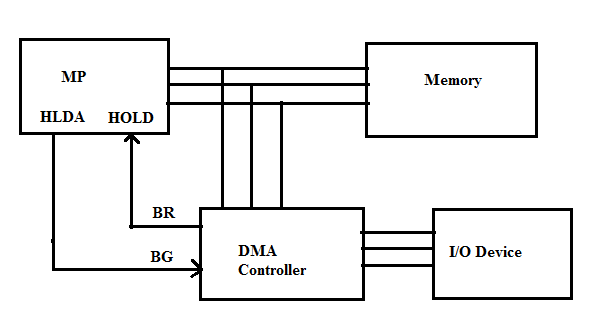
If playback doesnt begin shortly try restarting your. Up to 256 bytes can be pro-grammed per transfer. DRQ 0 to DRQ 3 Pin number 16 to 19 These pins get enabled whenever the input device requests the DMA controller for direct data transfer to or from the main memory. The first is a 16 bit standard IO read. The DMA controller then takes over the control of the microprocessor system bus for the time that microprocessor is stopped.

The DMA controller then takes over the control of the microprocessor system bus for the time that microprocessor is stopped. The figure below shows the pin diagram of 8257 DMA controller. The PPM resulting of the internal source clock. Draw timing diagrams for a. Normal transfer of one data byte takes up to 29 clock cycles.

The registers in the DMA are selected by the MP through the address bus by enabling the DS DMA select and RS Register Select inputs. Prodigy 415 points. The PPM resulting of the internal source clock. The DMA controller then takes over the control of the microprocessor system bus for the time that microprocessor is stopped. DMA controller provides an.
 Source: slideshare.net
The device returning control of the bus to the CPU. The block diagram shows a logical pin out and internal registers of the 8237. The first is a 16 bit standard IO read. Timing diagram related to the write and read strobes while per-forming a DMA transfer involving external memory. First lets review DRAM access by referencing the timing diagram for a Texas Instruments 4464 64kbx4 Dynamic Random Access Memory DRAM in Figure 2 of the same type often installed in the CoCo3.
 Source: geeksforgeeks.org
The DMA controller then takes over the control of the microprocessor system bus for the time that microprocessor is stopped. The basic idea of DMA is to transfer blocks of data directly between memory and peripherals. CoCo12 DMA Write Example. The figure below shows the pin diagram of 8257 DMA controller. INHIBIT signal to LOW.

DMA stands for Direct Memory Access. DMA is one of the faster types of synchronization mechanisms. DMA stands for Direct Memory Access. Figure shows the block diagram of a typical DMA controller. A timing device such that after preset time interval is set an event must occur during.
 Source: cs.uni.edu
A device becoming bus master. Block diagram of an Embedded System. As can be seen in the timing diagram there are a few clock cycles between the time that HOLD changes and until HLDA changes HLDA output is a signal to the requesting device that the processor has relinquished control of its memory and IO space. A timing device such that after preset time interval is set an event must occur during. The registers in the DMA are selected by the MP through the address bus by enabling the DS DMA select and RS Register Select inputs.
 Source: researchgate.net
It also shows the interface with the 8085 using a 3-to-8 decoder 8237 has four independent channels CH0-CH3. First lets review DRAM access by referencing the timing diagram for a Texas Instruments 4464 64kbx4 Dynamic Random Access Memory DRAM in Figure 2 of the same type often installed in the CoCo3. DMA Timing REF DESCRIPTION DRIVER RECEIVER MIN MAX MIN MAX 1 MEMR pulse width 214 203 2 SA setup to MEMR 81 70 3 SA hold from MEMR 36 25 4 IOCHRDY deasserted from MEMR 81 159 5 MEMR deasserted from IOCHRDY 125 125 6 REFRESH setup to MEMR 125 114 7 REFRESH hold from MEMR Note 1 31 250 20 239. ISA Bus Timing Diagrams 10 Figure 6. The data dont go through the microprocessor but the data bus is occupied.
 Source: slidetodoc.com
DMA Controller Direct Memory Access DMA is one of several methods for coordinating the timing of data transfers between an inputoutput IO device and the core processing unit or memory in a computer. Using cycle stealing data is transferred 1 byte at a time. The figure below shows the pin diagram of 8257 DMA controller. Normal transfer of one data byte takes up to 29 clock cycles. And the DMA mode block single byte etc Write a control word in the command register that specifies parameters such as priority among four Channels DREQ and DACK active levels and timing and enables the 8237 Write the starting address of the data block to.

Shown here the address and data lines are activated by the DMA engine during the entire computer cycle along with the enabled RW line. Two 16-bit registers are internally associated with each channel These registers. Timing diagram related to the write and read strobes while per-forming a DMA transfer involving external memory. A device becoming bus master. And the DMA mode block single byte etc Write a control word in the command register that specifies parameters such as priority among four Channels DREQ and DACK active levels and timing and enables the 8237 Write the starting address of the data block to.
 Source: slideshare.net
Asynchronous Memory Cycle Timing Diagramm for DMA from an Dual Port Memory. And the DMA mode block single byte etc Write a control word in the command register that specifies parameters such as priority among four Channels DREQ and DACK active levels and timing and enables the 8237 Write the starting address of the data block to. 58 Real-time clock Real-time clock ticks System Heart Beats. Using cycle stealing data is transferred 1 byte at a time. DMA Controller Direct Memory Access DMA is one of several methods for coordinating the timing of data transfers between an inputoutput IO device and the core processing unit or memory in a computer.

DMA Timing REF DESCRIPTION DRIVER RECEIVER MIN MAX MIN MAX 1 MEMR pulse width 214 203 2 SA setup to MEMR 81 70 3 SA hold from MEMR 36 25 4 IOCHRDY deasserted from MEMR 81 159 5 MEMR deasserted from IOCHRDY 125 125 6 REFRESH setup to MEMR 125 114 7 REFRESH hold from MEMR Note 1 31 250 20 239. It also shows the interface with the 8085 using a 3-to-8 decoder 8237 has four independent channels CH0-CH3. DMA stands for Direct Memory Access and is a method of transferring data from the computers RAM to another part of the computer without processing it using the CPU. The PPM resulting of the internal source clock. Prodigy 415 points.

The DMA controller then takes over the control of the microprocessor system bus for the time that microprocessor is stopped. The unit communicates with the MP via the data bus and control lines. First lets review DRAM access by referencing the timing diagram for a Texas Instruments 4464 64kbx4 Dynamic Random Access Memory DRAM in Figure 2 of the same type often installed in the CoCo3. The DMA transfer requires only 5 clock cycles. DMA is one of the faster types of synchronization mechanisms.
 Source: deeprajbhujel.blogspot.com
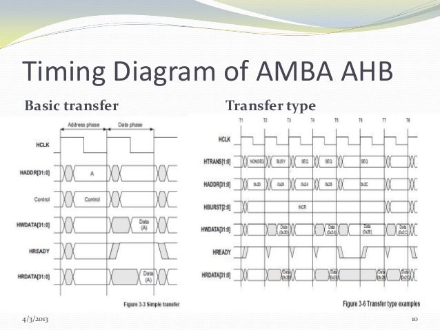
2 Exception An exception is any condition that needs. This timing diagram shows three different transfer cycles. It also shows the interface with the 8085 using a 3-to-8 decoder 8237 has four independent channels CH0-CH3. It allows the device to transfer the data directly tofrom memory without any interference of the CPU. The figure below shows the pin diagram of 8257 DMA controller.
 Source: researchgate.net
The device returning control of the bus to the CPU. The first is a 16 bit standard IO read. It allows the device to transfer the data directly tofrom memory without any interference of the CPU. DMA controller provides an. Timing diagram of input capture.
 Source: researchgate.net
This is followed by an almost identical 16 bit IO read with one wait state inserted. Block diagram of an Embedded System. Direct Memory Access DMA 8257 Basics Block Diagram Working Operation Watch later. The PPM resulting of the internal source clock. Two 16-bit registers are internally associated with each channel These registers.
This site is an open community for users to do submittion their favorite wallpapers on the internet, all images or pictures in this website are for personal wallpaper use only, it is stricly prohibited to use this wallpaper for commercial purposes, if you are the author and find this image is shared without your permission, please kindly raise a DMCA report to Us.
If you find this site adventageous, please support us by sharing this posts to your favorite social media accounts like Facebook, Instagram and so on or you can also save this blog page with the title dma timing diagram by using Ctrl + D for devices a laptop with a Windows operating system or Command + D for laptops with an Apple operating system. If you use a smartphone, you can also use the drawer menu of the browser you are using. Whether it’s a Windows, Mac, iOS or Android operating system, you will still be able to bookmark this website.