Dram block diagram
Home » Background » Dram block diagramYour Dram block diagram images are ready in this website. Dram block diagram are a topic that is being searched for and liked by netizens now. You can Find and Download the Dram block diagram files here. Download all free images.
If you’re searching for dram block diagram images information related to the dram block diagram topic, you have visit the right site. Our site frequently provides you with suggestions for refferencing the maximum quality video and image content, please kindly hunt and find more informative video content and images that fit your interests.
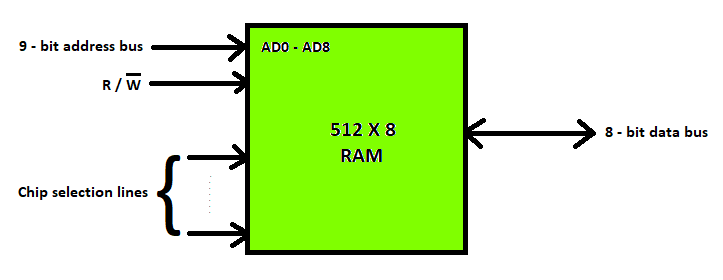
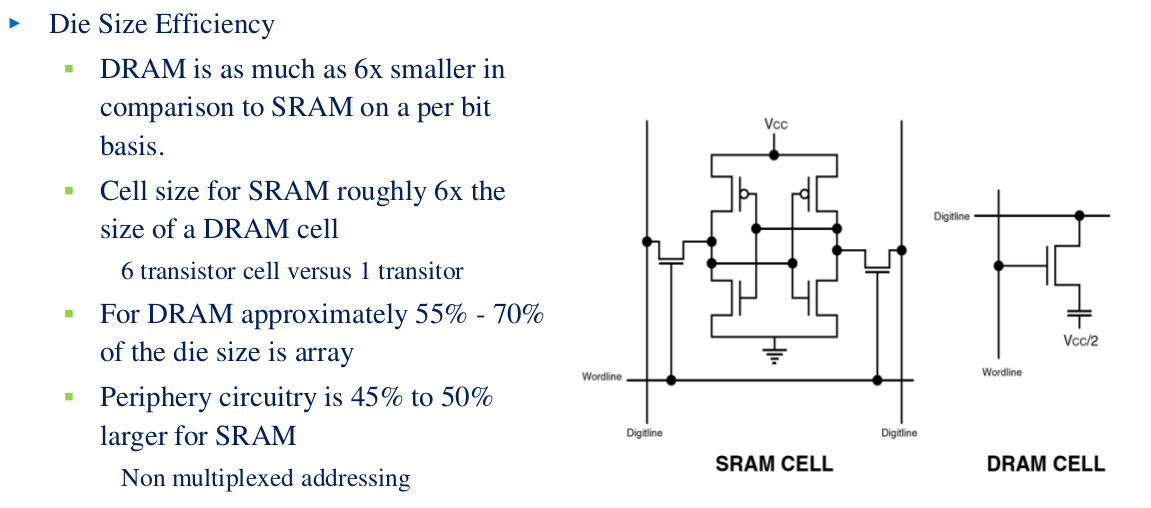
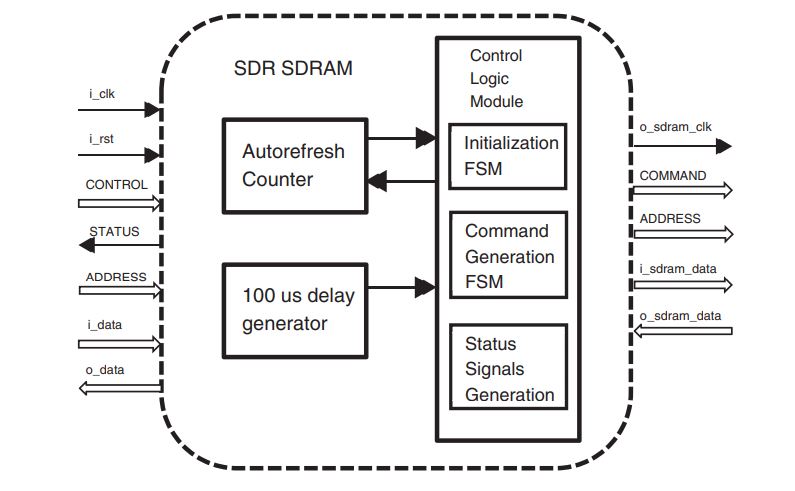
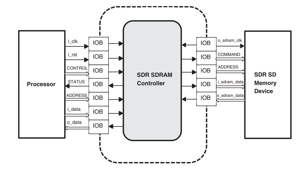
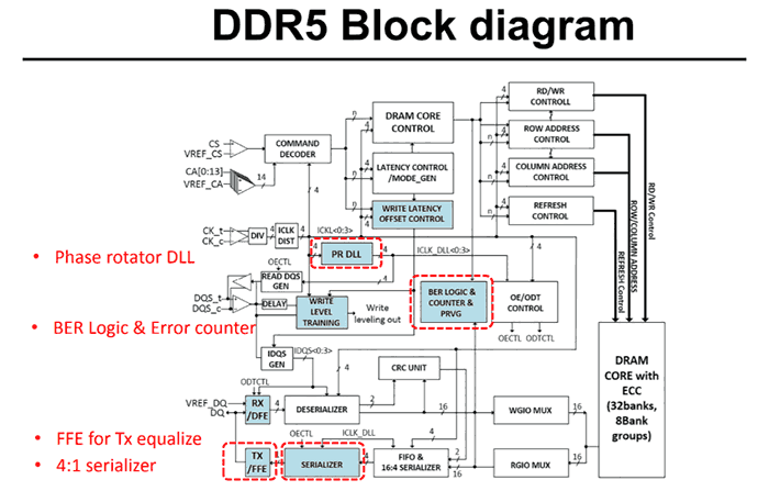
Dram Block Diagram. SRAM Die Size Efficiency DRAM is as much as 6x smaller in comparison to SRAM on a per bit basis. DRAM E 2 E 3 E 1 F A CPU Mem Controller A. A block diagram of a RAM unit is shown below. It stands for Static Random Access Memory.
 Different Types Of Ram Random Access Memory Geeksforgeeks From geeksforgeeks.org
As an example there may be a fault in a row address decoder that produces a DRAM failure mode of. The two control inputs specify the direction of transfer desired. Functional Block Diagrams Figure 2. DRAMDynamic RAM The block diagram of RAM chip is given below. SRAM memories are used to build Cache Memory. CS1 WE OE 6264 8K 8 SRAM CS1 CS2 WE OE Addr 1 2 Data write 1read 2.
DRAM E 2 E 3 E 1 F A CPU Mem Controller A.
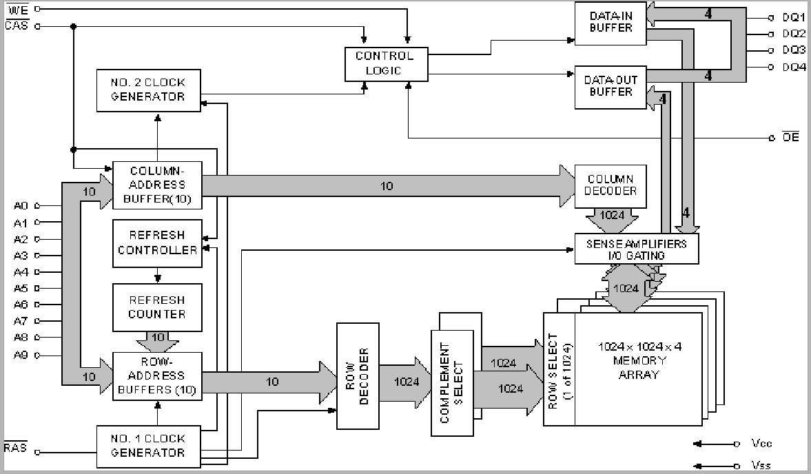
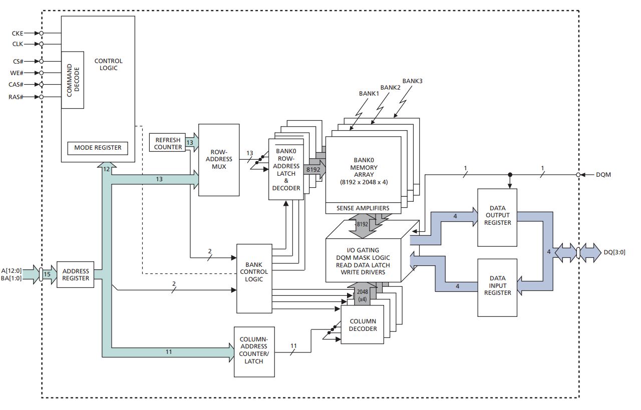
Includes separate capacitors to store each bit of data. An examination of the 32 Meg x 4 SDR and DDR functional block diagrams reveals that the memory core is essentially the same see Figure 1. Commands Sent to DRAM E 1. DRAM Design Overview Junji Ogawa DRAM Design Overview Stanford University Junji Ogawa jogawacisstanfordedu Feb. 1M BLOCK 2 1M BLOCK 3 1M BLOCK 4 1M BLOCK 5 1M BLOCK 6 1M BLOCK 7 1M BLOCK 8 1M BLOCK 9 1M BLOCK 10 1M BLOCK 11 1M BLOCK 26 1M BLOCK 27 1M BLOCK 28. Basic DRAM read and write cycles.
 Source: cl.cam.ac.uk
The two control inputs specify the direction of transfer desired. It is a slow process. We add two new components in DRAM chip. The sda_cl_bus AXI-lite interface accesses a 1KiB RAM inside the CL_SDA_SLV module. As an example there may be a fault in a row address decoder that produces a DRAM failure mode of.
 Source: cl.cam.ac.uk
1k x 8 RAM 10 addr lines 8-bit bytes 210 1k 1024 mem locations length width 8-bit size 1k-byte 8k-bits ECE 410 Prof. The SRAM memories consist of circuits capable of retaining the stored information as long as the power is applied. Commands Sent to DRAM E 1. Requires RAS CAS or F. DRAM E 2 E 3 E 1 F A CPU Mem Controller A.
 Source: researchgate.net
DRAM E 2 E 3 E 1 F A CPU Mem Controller A. 978-81-927147-8-3 100 Row addresses are present on address pads and are internally validated by the RAS Row Address Access clock. It is consist of banks rows and columns. WE CAS RAS 4164 64K 1 DRAM. It stands for Static Random Access Memory.
 Source: researchgate.net
En block enable assert low used as chip enable CE for an SRAM chip Control Data IO Address Memory size. 978-81-927147-8-3 100 Row addresses are present on address pads and are internally validated by the RAS Row Address Access clock. DRAM address and control registers DACR0 and DACR1The DRAM. 256Mb x4 SDRAM functional block diagram. Functional Block Diagram 2 Meg x 4 Memory Array with SDR and DDR Interface DDR VS.
 Source: researchgate.net
Functional Block Diagram 128 Meg x 16 x 16 Banks x 1 Rank ACT_n CAS_nA15 RAS_nA16 WE_nA14 PAR VrefCA CK_t CK_c LDQ70 LDQS_t LDQS_c A130 BA10 BG10 Byte 0 64 Meg x 8 x 16 banks Byte 1 64 Meg x 8 x 16 banks 128 Meg x 16 x 16 banks CS_n CKE ODT UDM_nUZQ LZQ UDBI_n LDM_n LDBI_n TEN RESET_n. A Buffer Register and a MUX multiplexer. Much lower Cost DRAM vs. SRAM memories are used to build Cache Memory. Requires only a CAS or E 2.

Much lower Cost DRAM vs. AsynchronousSynchronous DRAM Controller Block Diagram The DRAM controllers major components shown in Figure 11-1 are described as follows. Commands Sent to DRAM E 1. Functional Block Diagram 2 Meg x 4 Memory Array with SDR and DDR Interface DDR VS. A block diagram of a RAM unit is shown below.
 Source: cs.cmu.edu
DRAMDynamic RAM The block diagram of RAM chip is given below. How does DRAM request a block of data. 1M BLOCK 2 1M BLOCK 3 1M BLOCK 4 1M BLOCK 5 1M BLOCK 6 1M BLOCK 7 1M BLOCK 8 1M BLOCK 9 1M BLOCK 10 1M BLOCK 11 1M BLOCK 26 1M BLOCK 27 1M BLOCK 28. The sda_cl_bus AXI-lite interface accesses a 1KiB RAM inside the CL_SDA_SLV module. A block diagram of a RAM unit is shown below.
 Source: firecontrolman.tpub.com
The Buffer Register is used to temporarily store the source row and the MUX is used to choose the write back data used in refresh period. It includes transistors to store a single bit of data. It stands for Static Random Access Memory. The SRAM memories consist of circuits capable of retaining the stored information as long as the power is applied. T OH t AA t RC t OH Address Dout CS Dout t CHZ t ACS t CLZ a with CS 0 OE 0 WE 1 b with address stable OE 0 WE 1 previous data valid data valid data valid Figure 9-4 Read Cycle Timing.
 Source: student-circuit.com
Quoted as the speed of a DRAM A fast 4Mb DRAM t RAC 60 ns t RC. The SRAM memories consist of circuits capable of retaining the stored information as long as the power is applied. Top-level block diagram of CL_DRAM_DMA. In SRAM a single block of memory requires six transistors whereas DRAM needs just one transistor for a single block of memory. Requires only a CAS or E 2.
 Source: slidetodoc.com
As an example there may be a fault in a row address decoder that produces a DRAM failure mode of. DRAM is named as dynamic because it uses capacitor which produces leakage current due to the dielectric used inside the capacitor to separate the conductive plates is not a perfect insulator hence require power refresh circuitry. It includes transistors to store a single bit of data. A Block Diagram usually means that you draw the main components of a circuitsystem with boxes pretend means in a box -amplifier–Analog to Digital Convertor–Output a Block. WE CAS RAS 4164 64K 1 DRAM.

1k x 8 RAM 10 addr lines 8-bit bytes 210 1k 1024 mem locations length width 8-bit size 1k-byte 8k-bits ECE 410 Prof. An examination of the 32 Meg x 4 SDR and DDR functional block diagrams reveals that the memory core is essentially the same see Figure 1. DRAM E 2 E 3 E 1 F A CPU Mem Controller A. Minimu m time fro m the sta rt of o ne row ac cess to the start of th e next. The left side of the diagram shows five major incoming interfaces from Shell to CL.
 Source: geeksforgeeks.org
Functional Block Diagram 128 Meg x 16 x 16 Banks x 1 Rank ACT_n CAS_nA15 RAS_nA16 WE_nA14 PAR VrefCA CK_t CK_c LDQ70 LDQS_t LDQS_c A130 BA10 BG10 Byte 0 64 Meg x 8 x 16 banks Byte 1 64 Meg x 8 x 16 banks 128 Meg x 16 x 16 banks CS_n CKE ODT UDM_nUZQ LZQ UDBI_n LDM_n LDBI_n TEN RESET_n. Transaction request may be delayed in Queue B. It is consist of banks rows and columns. As an example there may be a fault in a row address decoder that produces a DRAM failure mode of. Functional Block Diagram 2 Meg x 4 Memory Array with SDR and DDR Interface DDR VS.
 Source: slidetodoc.com
DRAM address and control registers DACR0 and DACR1The DRAM. Transaction converted to Command Sequences may be queued D. DRAM E 2 E 3 E 1 F A CPU Mem Controller A. Bytes N bits N n Example. The sda_cl_bus AXI-lite interface accesses a 1KiB RAM inside the CL_SDA_SLV module.
 Source: researchgate.net
The Buffer Register is used to temporarily store the source row and the MUX is used to choose the write back data used in refresh period. Ownership of Micron Inc. 1 An Introduction to DRAM C decoders in the block diagram have two purposes. That means this type of memory requires constant power. As an example there may be a fault in a row address decoder that produces a DRAM failure mode of.
 Source: student-circuit.com
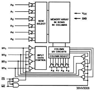
The level VTRIP an idealized trip point around which the input buffers slice the input. WE CAS RAS 4164 64K 1 DRAM. 6264 SRAM Block Diagram CY6264-1 A1 A2 A 3 A4 A5 A. It is consist of banks rows and columns. DRAM is named as dynamic because it uses capacitor which produces leakage current due to the dielectric used inside the capacitor to separate the conductive plates is not a perfect insulator hence require power refresh circuitry.
 Source: student-circuit.com
SDRAM bus width can be x8. Functional Block Diagrams Figure 2. Simplified DRAM block diagram. SDRAM bus width can be x8. An examination of the 32 Meg x 4 SDR and DDR functional block diagrams reveals that the memory core is essentially the same see Figure 1.
 Source: edux.pjwstk.edu.pl
Transaction request may be delayed in Queue B. DRAM address and control registers DACR0 and DACR1The DRAM. Basic DRAM read and write cycles. It stands for Dynamic Random Access Memory. The left side of the diagram shows five major incoming interfaces from Shell to CL.
 Source: hexus.net
Does not require periodically refreshment to maintain data. Functional Block Diagrams Figure 2. Figure 9-3 Block Diagram of 6116 Static RAM. Modern SDRAM runs at 33V having clock rates from 133MHz up to 200 MHz. DRAM Design Overview Junji Ogawa DRAM Design Overview Stanford University Junji Ogawa jogawacisstanfordedu Feb.
This site is an open community for users to share their favorite wallpapers on the internet, all images or pictures in this website are for personal wallpaper use only, it is stricly prohibited to use this wallpaper for commercial purposes, if you are the author and find this image is shared without your permission, please kindly raise a DMCA report to Us.
If you find this site value, please support us by sharing this posts to your own social media accounts like Facebook, Instagram and so on or you can also bookmark this blog page with the title dram block diagram by using Ctrl + D for devices a laptop with a Windows operating system or Command + D for laptops with an Apple operating system. If you use a smartphone, you can also use the drawer menu of the browser you are using. Whether it’s a Windows, Mac, iOS or Android operating system, you will still be able to bookmark this website.