Dyn11 transformer connection diagram
Home » Wallpapers » Dyn11 transformer connection diagramYour Dyn11 transformer connection diagram images are available. Dyn11 transformer connection diagram are a topic that is being searched for and liked by netizens today. You can Get the Dyn11 transformer connection diagram files here. Find and Download all royalty-free photos.
If you’re searching for dyn11 transformer connection diagram pictures information linked to the dyn11 transformer connection diagram interest, you have visit the right site. Our website always gives you hints for refferencing the highest quality video and image content, please kindly search and locate more enlightening video content and graphics that match your interests.
Dyn11 Transformer Connection Diagram. This phase displacement will result in the misoperation of differential protection if left uncompensated. Transformer dyn11 connection diagram electrical systems transformer vector groups. Delta star transformer connection overview. The phase-bushings on a three phase transformer are marked either ABC UVW or 123 HV-side capital LV-side small letters.

In the winding connection diagram a2 is connected to b1 so in the phasor diagram a2 and b1 are joined. Transformer Dyn11 Connection Diagram Keywords. In the three-phase transformer we can change the transformation by going from star to delta connection. Y-Y Y- -Y and -. The secondary side is Star with Neutral Connection denoted by yn. We have three transformers vector group DYN11 1004kV.
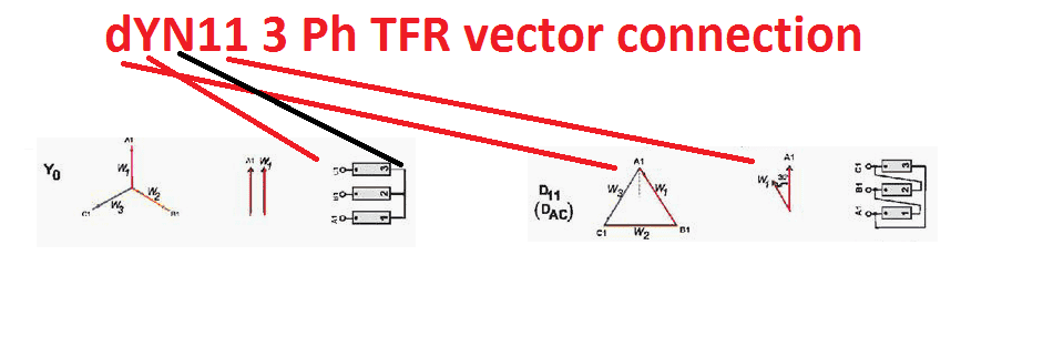
Dyn11 is vector group notation of tansformerIt means LV windingwhich is star connected written in small letters means LV side and vice versais 30 degrees lagging by HV winding which is delta connectedIn India we go for -30 deg connection of transformer.
When a single unit or bank of three is used there are four types of connections. Schematic diagram of a three-phase transformer. Dy11 signifies a Delta Primary primary has an upper case letter Wye secondary secondary has a lower case letter and the orientation of the 3 phase diagram relative to the A. What is standby earth fault protection and how it is to be. According to most standards transformer coils are classed as either Delta D Wye Y or Zigzag Z. In this article CT connection for transformer differential protection will be discussed.

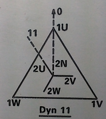
The following information is obtained from the Vector diagram. The four basic connections are. This gives us mixed connections. Transformer Dyn11 Connection Diagram Author. Electrical notes electrical notes amp articles.
 Source: forum.huawei.com
Transformer Name Plate. So to make the system highly efficient delta winding is used at LV. Side while star is used at. Dyn11 30 displacement between HV and LV. Electrical notes electrical notes amp articles.
 Source: electrical4u.com
Transformer Dyn11 Connection Diagram Electric power amp transmission amp distribution FAQ April 21st 2019 - Thus an internal connected Dyn1 transformer can be changed to either a Dyn3 Dyn5 Dyn7 Dyn9 or Dyn11 transformer by doing external changes on both sides of the trsf This is just true for star delta or delta star connections Changes for delta. In the case of mixed connections the ratio between the main voltages on the primary and secondary sides is not equal to the ratio between the number of turns. The secondary side of a distribution transformer must be yn or zn to provide the neutral. The primary side is Delta denoted by D. Abb ret650 applications manual pdf download.
 Source: pacbasics.org
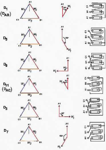
A Dyn11 for example indicates that the LV leads the HV by 30 therefore the HV winding should be DAC connected. The secondary side of a distribution transformer must be yn or zn to provide the neutral. The phase-bushings on a three phase transformer are marked either ABC UVW or 123 HV-side capital LV-side small letters. This gives us mixed connections. Transformer dyn11 connection diagram electrical systems transformer vector groups.
 Source: pydgrid.readthedocs.io
In the three-phase transformer we can change the transformation by going from star to delta connection. The DAC connection is characterized by line currents lagging the phase currents by 30. Electrical notes electrical notes amp articles. The previous discussion on the transformer vector group showed how transformer connection can cause phase displacement between the HV and LV winding. Y-Y Y- -Y and -.

D Delta connection at primaryy Star connection at secondary and n neutral point. Transformer Dyn11 Connection Diagram Author. March 21 2012 at 1. We have three transformers vector group DYN11 1004kV. Side while star is used at.
 Source: electrical-engineering-portal.com
Dyn11 transformer is widely used because in the transmission of power at some points voltage is stepped up and at some times voltage is stepped down. By doing some unconventional connections externally on one side of the Transformer an internal connected Dyn1 transformer can be changed either to a Dyn5-150 or Dyn990 connection. Y-Y Y- -Y and -. Transformer Dyn11 Connection Diagram Keywords. Dyn11 is vector group notation of tansformerIt means LV windingwhich is star connected written in small letters means LV side and vice versais 30 degrees lagging by HV winding which is delta connectedIn India we go for -30 deg connection of transformer.
 Source: researchgate.net
Answer 1 of 10. Transformer Dyn11 Connection Diagram Electric power amp transmission amp distribution FAQ April 21st 2019 - Thus an internal connected Dyn1 transformer can be changed to either a Dyn3 Dyn5 Dyn7 Dyn9 or Dyn11 transformer by doing external changes on both sides of the trsf This is just true for star delta or delta star connections Changes for delta. So to make the system highly efficient delta winding is used at LV. The first symbol indicates the connection of the primary and the second symbol is the. The previous discussion on the transformer vector group showed how transformer connection can cause phase displacement between the HV and LV winding.
 Source: sanjaysah.com.np
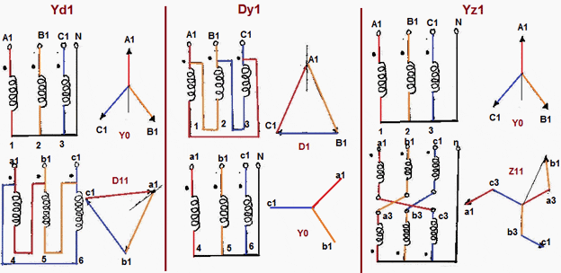
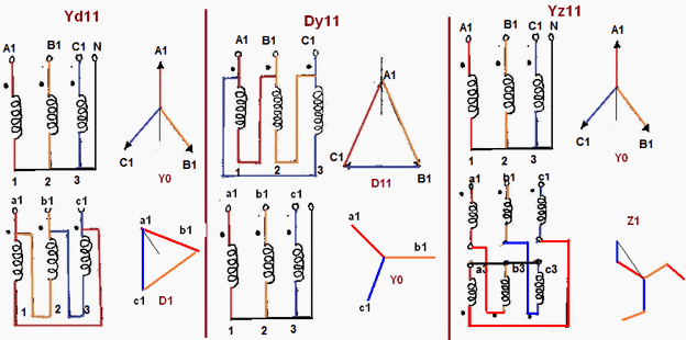
As shown in the figure the Vector Group is Dyn11. Transformer Dyn11 Connection Diagram Author. Transformer dyn11 connection diagram electrical systems transformer vector groups. As shown in the figure the Vector Group is Dyn11. The following information is obtained from the Vector diagram.
 Source: pacbasics.org
The four basic connections are. Dyn11 transformer is widely used because in the transmission of power at some points voltage is stepped up and at some times voltage is stepped down. Delta star transformer connection overview. As shown in the figure the Vector Group is Dyn11. Transformer Dyn11 Connection Diagram Keywords.
 Source: researchgate.net
Abb ret650 applications manual pdf download. Dyn11 30 displacement between HV and LV. Transformer Dyn11 Connection Diagram Keywords. The following are the mostly used Vector groups of transformers. The first symbol indicates the connection of the primary and the second symbol is the.
 Source: ect.lanchadirectly.pw
Vector group means it defines the primary secondary side connection type of the transformer. Transformer Dyn11 Connection Diagram Author. Similarly by joining other two phasors according to their winding connection we will automatically get the above phasor diagram. D Delta connection at primaryy Star connection at secondary and n neutral point. This gives us mixed connections.
 Source: researchgate.net
Dyn11 is vector group notation of tansformerIt means LV windingwhich is star connected written in small letters means LV side and vice versais 30 degrees lagging by HV winding which is delta connectedIn India we go for -30 deg connection of transformer. Transformer Name Plate. The star points of the transformers are connected to ground on the low voltage side. Transformer Dyn11 Connection Diagram Author. By doing some unconventional connections externally on one side of the Transformer an internal connected Dyn1 transformer can be changed either to a Dyn5-150 or Dyn990 connection.
 Source: youtube.com
When a single unit or bank of three is used there are four types of connections. All three transformers are supplied from the same medium voltage substation and each of them feeds one low voltage distribution. Answer 1 of 10. The below-mentioned diagram can be used for better understanding about transformer vector grouping and its usage. Transformer Dyn11 Connection Diagram Electric power amp transmission amp distribution FAQ April 21st 2019 - Thus an internal connected Dyn1 transformer can be changed to either a Dyn3 Dyn5 Dyn7 Dyn9 or Dyn11 transformer by doing external changes on both sides of the trsf This is just true for star delta or delta star connections Changes for delta.
 Source: electengmaterials.com
The primary side is Delta denoted by D. The first symbol indicates the connection of the primary and the second symbol is the. The DAC connection is characterized by line currents lagging the phase currents by 30. The secondary side of a distribution transformer must be yn or zn to provide the neutral. Vector group means it defines the primary secondary side connection type of the transformer.
 Source: sanjaysah.com.np
Dyn11 is vector group notation of tansformerIt means LV windingwhich is star connected written in small letters means LV side and vice versais 30 degrees lagging by HV winding which is delta connectedIn India we go for -30 deg connection of transformer. A three-phase transformer is built for a specific connection and voltage transformation and the unit will have a nameplate with the internal connections shown. The below-mentioned diagram can be used for better understanding about transformer vector grouping and its usage. All three transformers are supplied from the same medium voltage substation and each of them feeds one low voltage distribution. Dy11 signifies a Delta Primary primary has an upper case letter Wye secondary secondary has a lower case letter and the orientation of the 3 phase diagram relative to the A.
 Source: researchgate.net
This gives us mixed connections. Transformer Dyn11 Connection Diagram Author. In this article CT connection for transformer differential protection will be discussed. Transformer Dyn11 Connection Diagram Keywords. The secondary side of a distribution transformer must be yn or zn to provide the neutral.
 Source: electrical4u.net
The star points of the transformers are connected to ground on the low voltage side. Electrical notes electrical notes amp articles. Knowing the type of delta connection is very helpful in understanding the vector groups Dyn1 Dyn11 YNd1 and YNd11. In the three-phase transformer we can change the transformation by going from star to delta connection. Dy11 signifies a Delta Primary primary has an upper case letter Wye secondary secondary has a lower case letter and the orientation of the 3 phase diagram relative to the A.
This site is an open community for users to submit their favorite wallpapers on the internet, all images or pictures in this website are for personal wallpaper use only, it is stricly prohibited to use this wallpaper for commercial purposes, if you are the author and find this image is shared without your permission, please kindly raise a DMCA report to Us.
If you find this site good, please support us by sharing this posts to your favorite social media accounts like Facebook, Instagram and so on or you can also bookmark this blog page with the title dyn11 transformer connection diagram by using Ctrl + D for devices a laptop with a Windows operating system or Command + D for laptops with an Apple operating system. If you use a smartphone, you can also use the drawer menu of the browser you are using. Whether it’s a Windows, Mac, iOS or Android operating system, you will still be able to bookmark this website.