Electronic choke circuit diagram for 40w tube light
Home » Wallpapers » Electronic choke circuit diagram for 40w tube lightYour Electronic choke circuit diagram for 40w tube light images are ready in this website. Electronic choke circuit diagram for 40w tube light are a topic that is being searched for and liked by netizens now. You can Find and Download the Electronic choke circuit diagram for 40w tube light files here. Get all free photos.
If you’re searching for electronic choke circuit diagram for 40w tube light images information connected with to the electronic choke circuit diagram for 40w tube light keyword, you have pay a visit to the ideal site. Our website always provides you with hints for viewing the highest quality video and image content, please kindly surf and find more informative video content and images that match your interests.
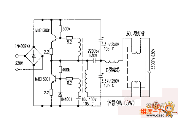
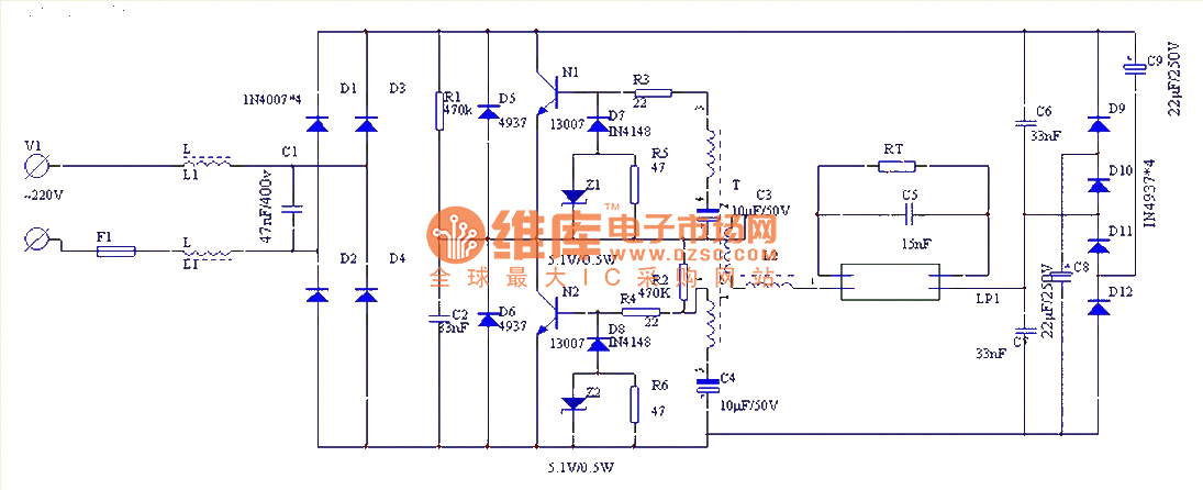
Electronic Choke Circuit Diagram For 40w Tube Light. Auto ballast tube light wiring connection find more details circuit schematics and the source code here. Cfl Light Circuit Diagram. Fluorescent Lamp Ballast Circuit Diagram Light Connection Diagram 40w Fluorescent Lamp Electronic Ballast Circuit 555 Diagram Seekic Com. This Article gives a details about double tube light connection by using single ballast or choke some electronic choke not support this connection check the ballast specification and watts level before make.
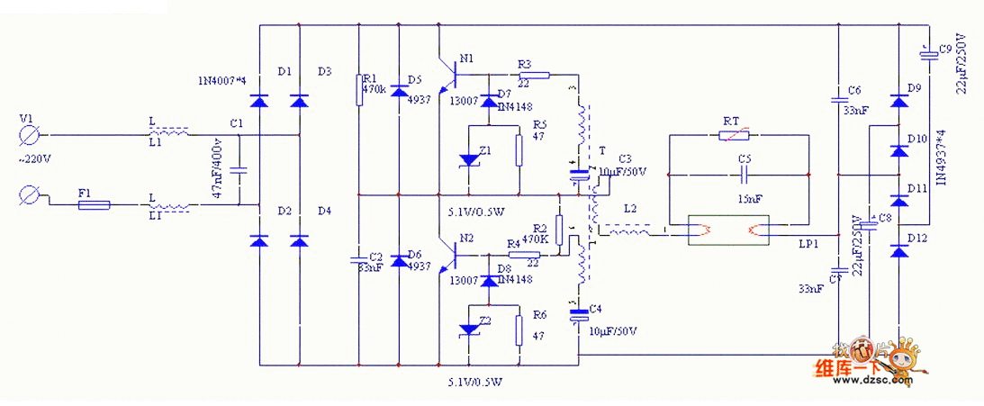 40w Fluorescent Lamp Electronic Ballast Circuit 555 Circuit Circuit Diagram Seekic Com From seekic.com
Electronic Ballast Tube light wiring diagram Connection and Working We need tube light ballast starter and fluorescent light holders to make wiring connection. Many thanks for visiting our website to locate Electronic Choke Wiring Diagram. Electronic Choke Circuit Electrical इल क ट र न च In Vijayawada Maruthi Lights Id 8054004230. The tube light or fluorescent light is a low pressure mercury vapor gas discharge lamp and it uses fluorescent to produce white light. Find every electronics circuit diagram here Categorized Electronic Circuits and Electronic Projects with well explained operation and how to make it procedure and then New Circuits every day Enjoy and Discover electronics. Electronic Choke Circuit Diagram For 40w Tube Light Free Pdf Books Electronic Choke Circuit Diagram For 40w Tube Light Electronic Choke Circuit Diagram For 40w Tube Light Free Without Downloading responses of networks and analysis of a three-phase circuit.
Although it operates at 230 V 50 Hz some auxiliary electrical components are used to insert in this installation to support the tube light operational principle.
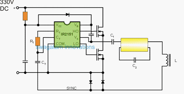
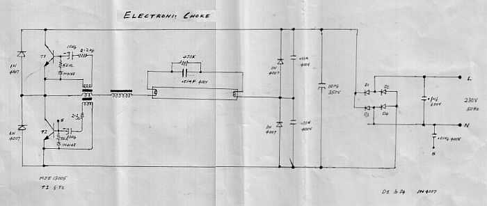
New Circuit for Electronic Choke for Tube Light At this paint the ballast ar choke Kick s back its stored current which again passes through the filament and ignites the tube light once again. A choke is connected in one end of the tube light and a starter is in series with the circuit. Electronic choke circuit diagram for 36w tube light. An electronic ballast will convert power frequency to a very high frequency to initialize the gas discharge process in Fluorescent Lamps. Saving in Energy Longevity of tu. Get More Great Videos - Subscribe.
 Source: homemade-circuits.com
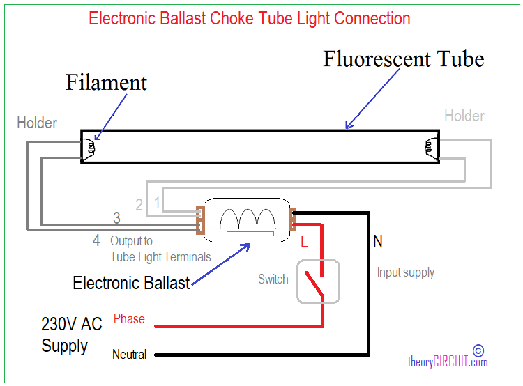
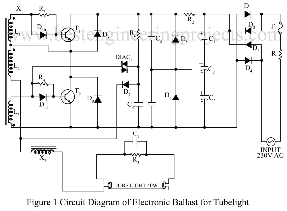
40 watt Electronic Ballast Circuit. Electronic ballast QTz8 2x36W OSRAM tube HF fluorescent 2x. As you see in the above diagram the Input of the electronic Choke is connected to the Switch Board for Power Supply. In this third edition two. This Compact lightweight high-frequency electronic ballast is designed to operate off the 230V AC mains supply at 50-60 Hz and is suitable for 36 40 W fluorescent tubesThe advantages of such a ballast are.
 Source: homemade-circuits.com
Here is no need of Tube Light Starter. Output 1 is connected to the right side filament and Output 2 is. Electronic Choke Circuit Electrical इल क ट र न च In Vijayawada Maruthi Lights Id 8054004230. An electronic ballast or electrical ballast is a device that controls the starting voltage and the operating currents of lighting devices. Electronic Ballast Tube light wiring diagram Connection and Working We need tube light ballast starter and fluorescent light holders to make wiring connection.
 Source: electronics-circuits.com
Tube light connection with electrical ballast and starter 2. Cfl Light Circuit Diagram. All we have t. This post fluorescent light wiring diagram tube light circuit is about how to wiring fluorescent light and how a fluorescent tube light works. When supply is provided the starter will interrupt the supply cycle of AC.
 Source: tips-trick-electronic.blogspot.com
Double Tube Light Circuit Diagram. Here is no need of Tube Light Starter. Tube light connection with electrical ballast and starter 2. This Compact lightweight high-frequency electronic ballast is designed to operate off the 230V AC mains supply at 50-60 Hz and is suitable for 36 40 W fluorescent tubesThe advantages of such a ballast are. Electronic Ballast Tube light wiring diagram Connection and Working We need tube light ballast starter and fluorescent light holders to make wiring connection.
 Source: homemade-circuits.com
This post fluorescent light wiring diagram tube light circuit is about how to wiring fluorescent light and how a fluorescent tube light works. An electronic ballast will convert power frequency to a very high frequency to initialize the gas discharge process in Fluorescent Lamps. Circuit of a 40W fluorescent tube with 40W Ballast and starter. Tube Light connection diagram. Working Principle of Tube Light.
 Source: circuitsdiy.com
Tube light connection with electrical ballast and starter 2. It can also be achieved by heating the gas. This Compact lightweight high-frequency electronic ballast is designed to operate off the 230V AC mains supply at 50-60 Hz and is suitable for 36 40 W fluorescent tubesThe advantages of such a ballast are. Electronic choke circuit diagram for 36w tube light. Get More Great Videos - Subscribe.
 Source: selmaasci.com
It does this through the principle of electrical gas discharge. String led circuit diagram constant current power supply. Electronic choke has one input and two output. Circuit diagram electronic ballast for 40W light Fluorescent BALLAST low loss G24D 40w ELECTRONIC choke circuit DIAGRAM conventional fluorescent lamp starter. Find every electronics circuit diagram here Categorized Electronic Circuits and Electronic Projects with well explained operation and how to make it procedure and then New Circuits every day Enjoy and Discover electronics.
 Source: theorycircuit.com
Cfl Light Circuit Diagram. Electronic Ballast Tube light wiring diagram Connection and Working We need tube light ballast starter and fluorescent light holders to make wiring connection. New Circuit for Electronic Choke for Tube Light At this paint the ballast ar choke Kick s back its stored current which again passes through the filament and ignites the tube light once again. String led circuit diagram constant current power supply. 14 Tube Light Connection Diagram With Electronic Choke.
 Source: next.gr
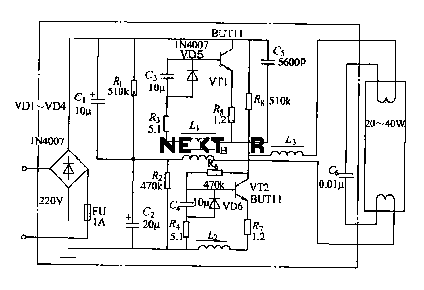
Fluorescent Lamp Ballast Circuit Diagram Light Connection Diagram 40w Fluorescent Lamp Electronic Ballast Circuit 555 Diagram Seekic Com. Auto ballast tube light wiring connection find more details circuit schematics and the source code here. Electronic Choke Circuit Diagram For 40w Tube Light Free Pdf Books Electronic Choke Circuit Diagram For 40w Tube Light Electronic Choke Circuit Diagram For 40w Tube Light Free Without Downloading responses of networks and analysis of a three-phase circuit. Circuit of a 40W fluorescent tube with 40W Ballast and starter. Tube light wiring diagram.
 Source: selmaasci.com
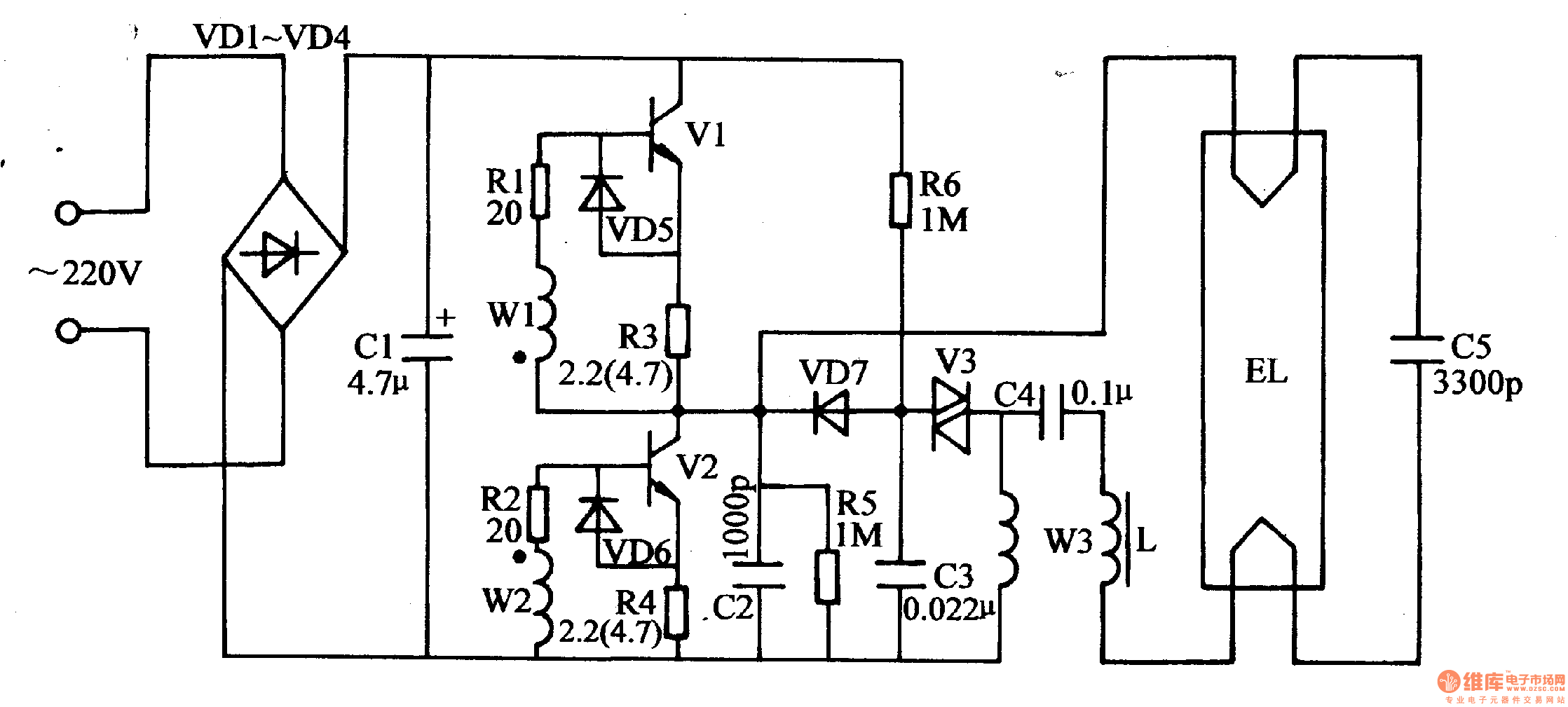
In this third edition two. The connection diagram of Tube Light with Electronic Choke is very simple. Many thanks for visiting our website to locate Electronic Choke Wiring Diagram. A choke is connected in one end of the tube light and a starter is in series with the circuit. 1973 Corvette Wiring Diagrams Free.
 Source: bestengineeringprojects.com
Find every electronics circuit diagram here Categorized Electronic Circuits and Electronic Projects with well explained operation and how to make it procedure and then New Circuits every day Enjoy and Discover electronics. Saving in Energy Longevity of tu. Electronic Choke Circuit Diagram For 40w Tube Light Free Pdf Books Electronic Choke Circuit Diagram For 40w Tube Light Electronic Choke Circuit Diagram For 40w Tube Light Free Without Downloading responses of networks and analysis of a three-phase circuit. 1973 Corvette Wiring Diagrams Free. Find every electronics circuit diagram here Categorized Electronic Circuits and Electronic Projects with well explained operation and how to make it procedure and then New Circuits every day Enjoy and Discover electronics.
 Source: pinterest.com
A choke is connected in one end of the tube light and a starter is in series with the circuit. 1973 Corvette Wiring Diagrams Free. Answer 1 of 8. This Article gives a details about double tube light connection by using single ballast or choke some electronic choke not support this connection check the ballast specification and watts level before make. Electronic choke has one input and two output.
 Source: seekic.com
In this third edition two. 15 Tube Light Connection. Auto ballast tube light wiring connection find more details circuit schematics and the source code here. As you see in the above diagram the Input of the electronic Choke is connected to the Switch Board for Power Supply. Electronic choke circuit diagram for 36w tube light.
 Source: next.gr
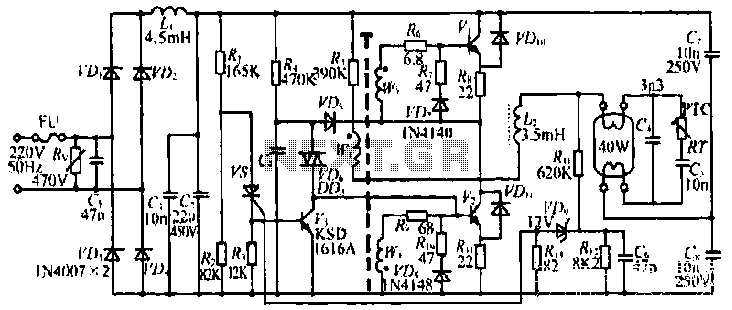
A choke is connected in one end of the tube light and a starter is in series with the circuit. It is electromagnetic ballast or electronic. This Article gives a details about double tube light connection by using single ballast or choke some electronic choke not support this connection check the ballast specification and watts level before make. Answer 1 of 8. Tube light connection circuit diagram.
 Source: pinterest.com
It does this through the principle of electrical gas discharge. In this third edition two. Get More Great Videos - Subscribe. Wrg 8228 workshop wiring diagrams 1920s h g fischer diathermy unit bd 0410 new circuit diagram rr 7988 block diagram iphone 4 download diagram 26 good electrical panel wiring diagram s fba volvo truck dash. A choke is connected in one end of the tube light and a starter is in series with the circuit.
 Source: seekic.com
Due to the sudden change of supply the chock will generate around 1000volts. Hopefully we provide this can be helpful for you. Many thanks for visiting our website to locate Electronic Choke Wiring Diagram. Here is no need of Tube Light Starter. It is electromagnetic ballast or electronic.
 Source: in.pinterest.com
These two are required to provide the initial high voltage for ionization and thereafter to limit. Here is no need of Tube Light Starter. In this third edition two. The connection diagram of Tube Light with Electronic Choke is very simple. Due to the sudden change of supply the chock will generate around 1000volts.
 Source: seekic.com
If you have other tools to achieve the same result then youre doing it right. A choke is connected in one end of the tube light and a starter is in series with the circuit. Here is no need of Tube Light Starter. Although it operates at 230 V 50 Hz some auxiliary electrical components are used to insert in this installation to support the tube light operational principle. Tube light connection circuit diagram.
This site is an open community for users to submit their favorite wallpapers on the internet, all images or pictures in this website are for personal wallpaper use only, it is stricly prohibited to use this wallpaper for commercial purposes, if you are the author and find this image is shared without your permission, please kindly raise a DMCA report to Us.
If you find this site good, please support us by sharing this posts to your preference social media accounts like Facebook, Instagram and so on or you can also save this blog page with the title electronic choke circuit diagram for 40w tube light by using Ctrl + D for devices a laptop with a Windows operating system or Command + D for laptops with an Apple operating system. If you use a smartphone, you can also use the drawer menu of the browser you are using. Whether it’s a Windows, Mac, iOS or Android operating system, you will still be able to bookmark this website.