Energy band diagram for pn junction diode
Home » Background » Energy band diagram for pn junction diodeYour Energy band diagram for pn junction diode images are available in this site. Energy band diagram for pn junction diode are a topic that is being searched for and liked by netizens today. You can Download the Energy band diagram for pn junction diode files here. Get all free images.
If you’re searching for energy band diagram for pn junction diode images information related to the energy band diagram for pn junction diode keyword, you have come to the ideal site. Our website frequently provides you with hints for seeking the maximum quality video and picture content, please kindly surf and find more informative video articles and graphics that fit your interests.
Energy Band Diagram For Pn Junction Diode. Energy Band Diagram Of P N Junction Diode Lessons Tes Teach. Comrades in this video we learn about the fabrication of P-N diodes and the Energy band diagram EBD of P-N diodes. Since the p-n junction demonstrates such a unipolar rectifying response to the applied voltage it is called a p-n diode and is denoted in circuit diagrams as a following symbol. Similar arguments apply to holes.
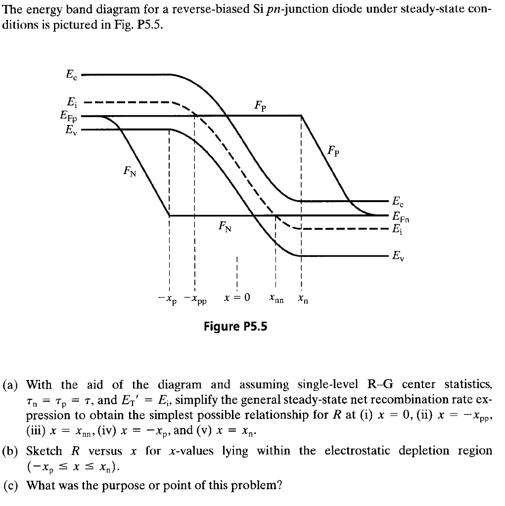 The Energy Band Diagram For A Reverse Biased Si Chegg Com From chegg.com
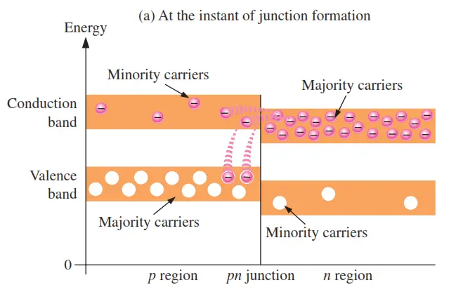
About Press Copyright Contact us Creators Advertise Developers Terms Privacy Policy Safety How YouTube works Test new features Press Copyright Contact us Creators. Energy band diagram of a p-n junction a before and b after merging the n-type and p-type regionsNote that this does not automatically align the Fermi energies E Fn and E Fp. Absorbing Materialorganic Polymer Autoelektrix Ru. Since the p-n junction demonstrates such a unipolar rectifying response to the applied voltage it is called a p-n diode and is denoted in circuit diagrams as a following symbol. An energy diagram for a pn junction at the instant of formation is shown in Figure a. Energy Band Scheme For The Impact Ionization Process For An.
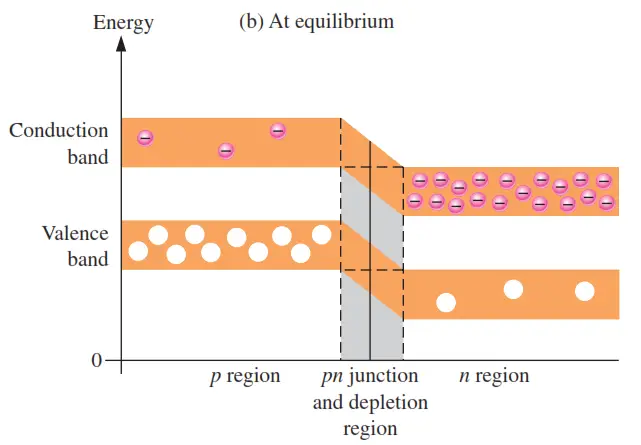
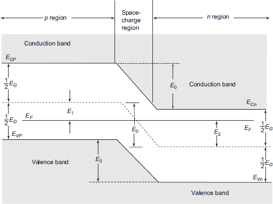
Energy Band Diagram at Thermal Equilibrium At thermal equilibrium Energy band diagram of a p-n junction in thermal equilibrium While in thermal equilibrium no external voltage is applied between the n-type and p-type material there is an internal potential f which is caused by the workfunction difference between the n-type and p-type pn.
The band diagram of isolated p-type and n-type materials are shown in Figs. No the energy band would not reverse. Also note that this flatband diagram is not an equilibrium diagram since both electrons and holes can lower their energy by crossing the junction. The green horizontal line is the Fermi level. Equilibrium band diagrams appear below the semiconductor. The energy band diagram of the pn junction under open circuit conditions is shown in Figure 611a.
 Source: shefalitayal.com
Energy Band Scheme For The Impact Ionization Process For An. No the energy band would not reverse. 813 Energy band diagram of p-n diode. Since the p-n junction demonstrates such a unipolar rectifying response to the applied voltage it is called a p-n diode and is denoted in circuit diagrams as a following symbol. 8 Draw The Energy Band Diagram Of An Unbiased P N Junction And.
 Source: physics.stackexchange.com
813 Energy band diagram of p-n diode. Since the p-n junction demonstrates such a unipolar rectifying response to the applied voltage it is called a p-n diode and is denoted in circuit diagrams as a following symbol. Comrades in this video we learn about the fabrication of P-N diodes and the Energy band diagram EBD of P-N diodes. Figure 112 shows the reverse bias energy band diagrams of a pn diode and a pBn diode calculated using heterojunction drift-diffusion simulation Daniel et al 2000. Similar arguments apply to holes.
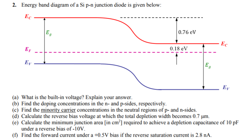 Source: chegg.com
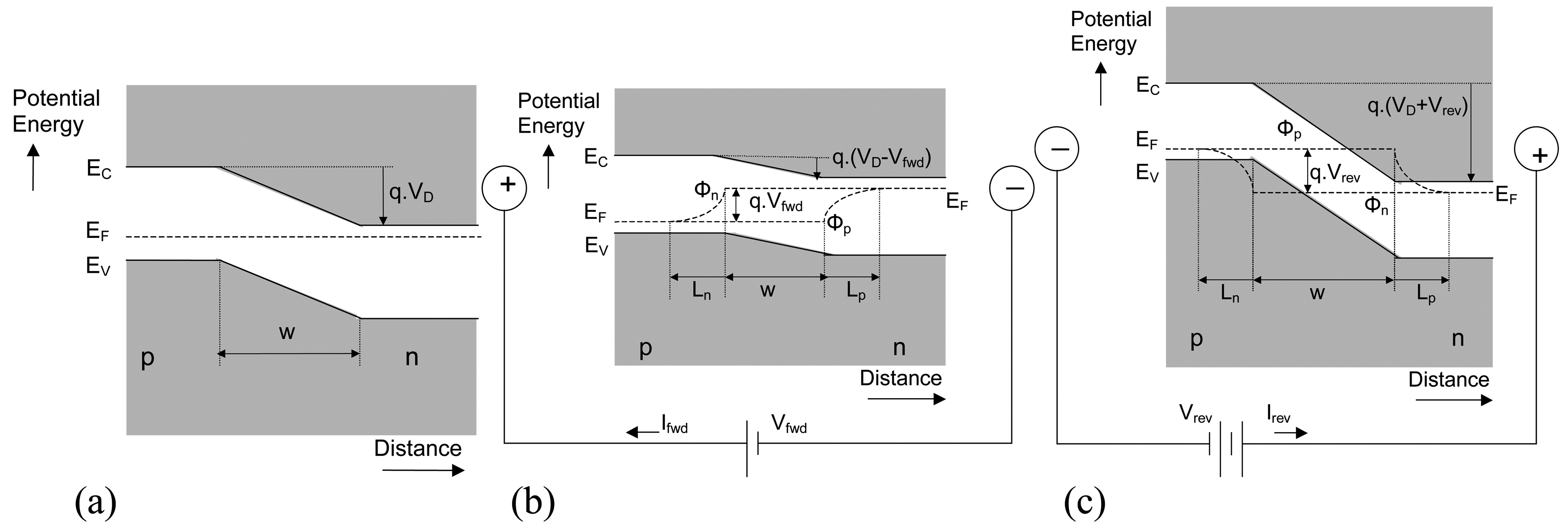
Also note that this flatband diagram is not an equilibrium diagram since both electrons and holes can lower their energy by crossing the junction. Energy Band Diagram of P-N Junction Diode. Energy bands are affected based on the biasing techniques applied. Absorbing Materialorganic Polymer Autoelektrix Ru. The Fermi levels vary when the diode is unbiased as well as it is forward biased or reverse biased.
 Source: instrumentationtools.com
The upward direction in the diagram represents increasing electron energy. As a convention we will assume E c to be positive if E cn E cp and E v to be positive if E vn E vp. The Fermi levels vary when the diode is unbiased as well as it is forward biased or reverse biased. Energy band diagram of a p-n junction a before and b after merging the n-type and p-type regions Note that this does not automatically align the Fermi energies E Fn and E Fp. Figure 2 1 The P N Junction Diode Showing Metal Anode And.
 Source: shefalitayal.com
Initiate the pn junction formation by clicking the FormJunction button or using mouse drag and watch the physical system approach a new electro-thermal equilibrium which is characterized by a constant Fermi level throughout the material. As a convention we will assume E c to be positive if E cn E cp and E v to be positive if E vn E vp. Energy Band Scheme For The Impact Ionization Process For An. Figure 112 shows the reverse bias energy band diagrams of a pn diode and a pBn diode calculated using heterojunction drift-diffusion simulation Daniel et al 2000. Initiate the pn junction formation by clicking the FormJunction button or using mouse drag and watch the physical system approach a new electro-thermal equilibrium which is characterized by a constant Fermi level throughout the material.
 Source: instrumentationtools.com
Simplified Energy Band Diagram Of A P N Junction A At. In a p on n structure this can be accomplished by inserting an electron-blocking unipolar barrier at the junction of the pn diode to form the pBn diode Klipstein 2008. As we increase the applied volatge the drop across the nuentral region increases such that the n side depletion region is always higher in potential to the p side depletion region. As you can see the valence and conduction bands in the n region are at lower energy levels than those in the p region but there is a significant amount of overlapping. 8 Draw The Energy Band Diagram Of An Unbiased P N Junction And.

8 Draw The Energy Band Diagram Of An Unbiased P N Junction And. 8 Draw The Energy Band Diagram Of An Unbiased P N Junction And. Equilibrium band diagrams appear below the semiconductor. The band diagram of isolated p-type and n-type materials are shown in Figs. About Press Copyright Contact us Creators Advertise Developers Terms Privacy Policy Safety How YouTube works Test new features Press Copyright Contact us Creators.
 Source: researchgate.net
The free electrons in the n region that occupy the upper part of the conduction band in. Comrades in this video we learn about the fabrication of P-N diodes and the Energy band diagram EBD of P-N diodes. About Press Copyright Contact us Creators Advertise Developers Terms Privacy Policy Safety How YouTube works Test new features Press Copyright Contact us Creators. Draw the energy band diagram of p-n junction diode in forward and reverse bias condition. As you can see the valence and conduction bands in the n region are at lower energy levels than those in the p region but there is a significant amount of overlapping.
 Source: hufmpatota.blogspot.com
Also note that this flatband diagram is not an equilibrium diagram since both electrons and holes can lower their energy by crossing the junction. Here are the timestamps so that you ca. 4381Band diagram of a heterojunction p-n diode under Flatband conditions The flatband energy band diagram of a heterojunction p-n diode is shown in the figure below. Electrons and holes reach an equilibrium at the junction and form a depletion region. An energy diagram for a pn junction at the instant of formation is shown in Figure a.
 Source: chegg.com
As you can see the valence and conduction bands in the n region are at lower energy levels than those in the p region but there is a significant amount of overlapping. There is no net current so the diffusion current of electrons from the n to p-side is balanced by the electron drift current from the p to n-side driven by the built-in field E0. Here are the timestamps so that you ca. Also note that this flatband diagram is not an equilibrium diagram since both electrons and holes can lower their energy by crossing the junction. As you can see the valence and conduction bands in the n region are at lower energy levels than those in the p region but there is a significant amount of overlapping.
 Source: slidetodoc.com
The upward direction in the diagram represents increasing electron energy. The upward direction in the diagram represents increasing electron energy. Energy band diagram of a p-n junction a before and b after merging the n-type and p-type regionsNote that this does not automatically align the Fermi energies E Fn and E Fp. A Sketch Of The Energy Band Structure Of A P N Junction Containing. The Fermi levels vary when the diode is unbiased as well as it is forward biased or reverse biased.
 Source: blendspace.com
No the energy band would not reverse. Energy Band Diagram of P-N Junction Diode. Energy Band Scheme For The Impact Ionization Process For An. The energy band diagram of the pn junction under open circuit conditions is shown in Figure 611a. Also note that this flatband diagram is not an equilibrium diagram since both electrons and holes can lower their energy by crossing the junction.
 Source: meudiariolivre.blogspot.com
Energy band diagram of a p-n junction a before and b after merging the n-type and p-type regions Note that this does not automatically align the Fermi energies E Fn and E Fp. Here are the timestamps so that you ca. Draw the energy band diagram of p-n junction diode in forward and reverse bias condition. This quick video will give you a complete analysis of energy band diagram of pn juction diode. The upward direction in the diagram represents increasing electron energy.

As you can see the valence and conduction bands in the n region are at lower energy levels than those in the p region but there is a significant amount of overlapping. As you can see the valence and conduction bands in the n region are at lower energy levels than those in the p region but there is a significant amount of overlapping. Energy Band of Unbiased Diode. 4381Band diagram of a heterojunction p-n diode under Flatband conditions The flatband energy band diagram of a heterojunction p-n diode is shown in the figure below. An energy diagram for a pn junction at the instant of formation is shown in figure a.
 Source: mdpi.com
Draw the energy band diagram of p-n junction diode in forward and reverse bias condition. Semiconductor Band Diagram P N Diode P N Junction. Comrades in this video we learn about the fabrication of P-N diodes and the Energy band diagram EBD of P-N diodes. Energy bands are affected based on the biasing techniques applied. The Fermi levels vary when the diode is unbiased as well as it is forward biased or reverse biased.
 Source: electronics-club.com
As you can see the valence and conduction bands in the n region are at lower energy levels than those in the p region but there is a significant amount of overlapping. Fig S5 Energy Band Diagram During Operation Of A Pn. Energy Band of Unbiased Diode. About Press Copyright Contact us Creators Advertise Developers Terms Privacy Policy Safety How YouTube works Test new features Press Copyright Contact us Creators. As you can see the valence and conduction bands in the n region are at lower energy levels than those in the p region but there is a significant amount of overlapping.
 Source: researchgate.net
Energy Band Diagram of P-N Junction Diode. Forward biasing increases the electron density in the conduction band of the n side. The energy band diagram language 3. About Press Copyright Contact us Creators Advertise Developers Terms Privacy Policy Safety How YouTube works Test new features Press Copyright Contact us Creators. The current voltage IV characteristic for the diode is rectifying and is very different from that.
 Source: slidetodoc.com
An energy diagram for a pn junction at the instant of formation is shown in Figure a. Cn vn vp Fp cp qf DE DE 0 Fn p qc i qc n E E E E E E E c v. The upward direction in the diagram represents increasing electron energy. The energy band diagram language 3. Absorbing Materialorganic Polymer Autoelektrix Ru.
This site is an open community for users to submit their favorite wallpapers on the internet, all images or pictures in this website are for personal wallpaper use only, it is stricly prohibited to use this wallpaper for commercial purposes, if you are the author and find this image is shared without your permission, please kindly raise a DMCA report to Us.
If you find this site serviceableness, please support us by sharing this posts to your preference social media accounts like Facebook, Instagram and so on or you can also save this blog page with the title energy band diagram for pn junction diode by using Ctrl + D for devices a laptop with a Windows operating system or Command + D for laptops with an Apple operating system. If you use a smartphone, you can also use the drawer menu of the browser you are using. Whether it’s a Windows, Mac, iOS or Android operating system, you will still be able to bookmark this website.