Fe cu phase diagram
Home » Background » Fe cu phase diagramYour Fe cu phase diagram images are ready. Fe cu phase diagram are a topic that is being searched for and liked by netizens now. You can Download the Fe cu phase diagram files here. Get all royalty-free images.
If you’re searching for fe cu phase diagram pictures information related to the fe cu phase diagram interest, you have pay a visit to the right site. Our site always provides you with suggestions for refferencing the maximum quality video and image content, please kindly hunt and find more enlightening video content and images that match your interests.
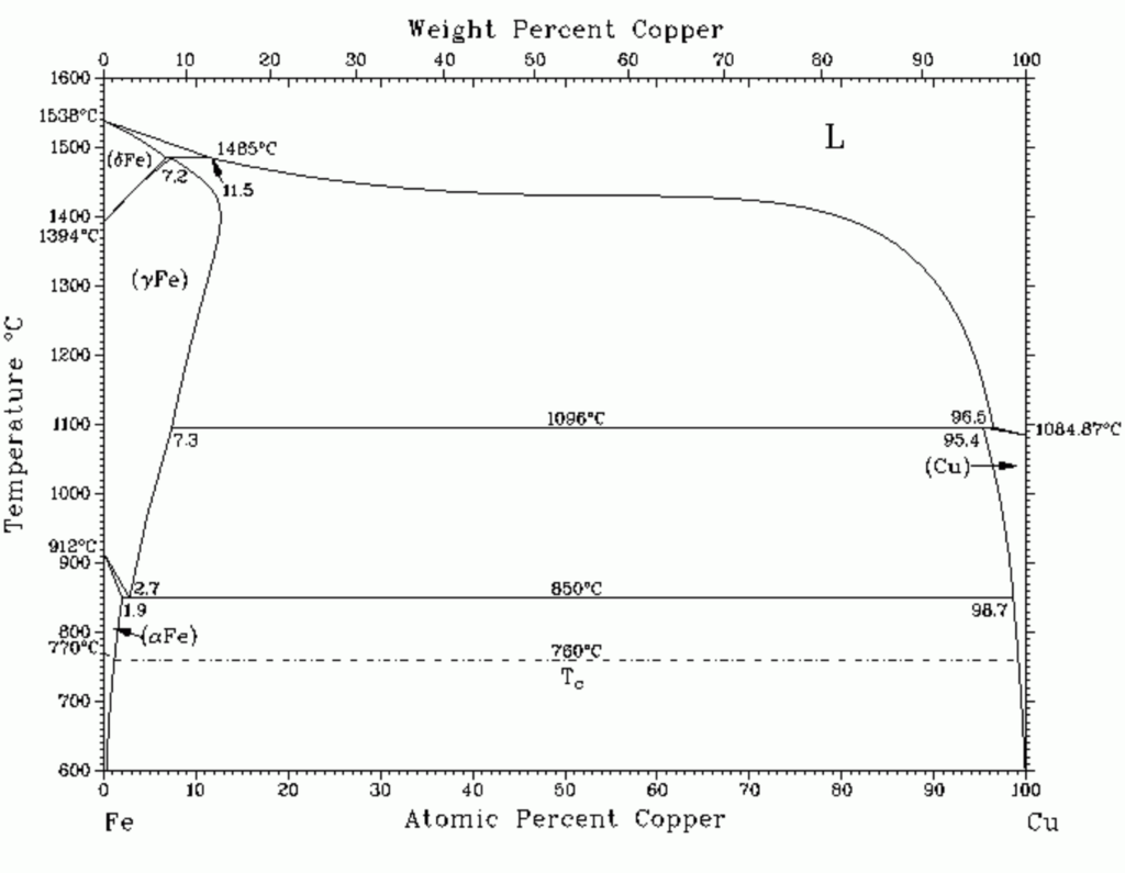
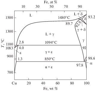
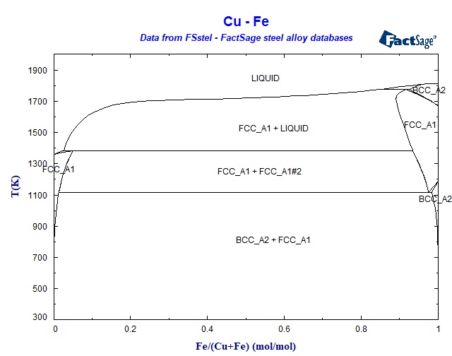
Fe Cu Phase Diagram. And is split at around 54wtCu by a particular phase. Weight Diagram 100. Iso-sulfur Activity Lines Cu-Fe-S System One Phase Region 98. Click on a system to display the phase diagram.
 Phase Diagram Of Iron Copper 22 Download Scientific Diagram From researchgate.net
4 the Fe-Co continuous solid solution is interrupted by the bcc phase. The minerals found in the Cu-Fe-S system appeared in this paper are listed in Table 1 together with its compositions abbreviations and their thermal stability. SGTE Alloy Phase Diagrams. Diagram Fasa dalam Sistem Logam - Fasa phase dalam terminologyistilah dalam mikrostrukturnya adalah suatu daerah region yang berbeda struktur atau komposisinya dari daerah lain. Log Pf126p2 Versus Composition of Matte Phase of Miscibility Gap. - Diagram fasa phase diagram adalah.
Ferrite Ferrite is the interstitial solid solution of carbon in alpha iron.
IRON-CARBON Fe-C PHASE DIAGRAM EXAMPLE 1 2 important points - Eutectoid B g aFe 3 C - Eutectic A L gFe 3 C Fe 3 e 1600 1400 1200 1000 800 600 400 0 1 2 3 4 5 6 67 L g austenite gL gFe 3 C aFe 3 C d Fe C wt C 1148ºC TºC a 727ºC Teutectoid 430 Result. The behavior of the copper-bearing solid solutions closely parallels that of pyrrhotite Toulmin and Barton 1964 in which the activity of FeS falls to 04 at a mole fraction of 09. These functions predict phase equilibria in close agreement with the experimental temperature-composition diagram and are represented in Fig. Click on a system to display the phase diagram. 93a is adapted from Phase Diagrams of Binary Nickel Alloys P. 4 the Fe-Co continuous solid solution is interrupted by the bcc phase.
 Source: researchgate.net
A crystalline phase diagram of a NdFeBCu sintered magnet up to 1100 C was determined through in-situ synchrotron X-ray diffraction using a new sample mounting method that prevents high-temperature contact reactions between the sample and the quartz capillary tube container. Iron allotropes showing the differences in lattice structure. Temperature and obtained the isothermal phase diagrams of the system Cu-Fe-S at 500C 400C 350C and 300C. FTmisc - FACT Sulfide Alloy Micellaneous Phase Diagrams. Click on a system to display the phase diagram.
 Source: himikatus.ru
Using this newly developed method we successfully observed almost identical phase diagrams. A with 1 at Cu excluding both graphite and diamond. δ-ferrite And phase mixtures 1. The Cu-Fe-Ti Copper-Iron-Titanium System in Phase Diagrams of Ternary Iron Alloys Part 6 Indian Institute of Metals Calcutta 1992 pp. A phase diagram is given for the CuFe-S join between 400 degrees and 700 degrees C.
 Source: researchgate.net
Iron allotropes showing the differences in lattice structure. The continuous face-centered cubic fcc solid solution between Fe and Co is labeled fcc 1 and the Cu-rich fcc phase is labeled fcc 2. Intermetallic phases are not named or but are. Log Pf126p2 Versus Composition of Matte Phase of Miscibility Gap. Detailed information is shown in Figs.
 Source: scielo.br
The behavior of the copper-bearing solid solutions closely parallels that of pyrrhotite Toulmin and Barton 1964 in which the activity of FeS falls to 04 at a mole fraction of 09. These functions predict phase equilibria in close agreement with the experimental temperature-composition diagram and are represented in Fig. Suatu diagram yang menunjukkan fasa dalam suatu sistem material diberbagai suhu tekanan dan komposisi. δ-ferrite And phase mixtures 1. And is split at around 54wtCu by a particular phase.
 Source: semanticscholar.org
A crystalline phase diagram of a NdFeBCu sintered magnet up to 1100 C was determined through in-situ synchrotron X-ray diffraction using a new sample mounting method that prevents high-temperature contact reactions between the sample and the quartz capillary tube container. When the liquid phase is supercooled it shows a metastable liquid miscibility gap. The metastable and stable phase diagrams of the Fe-C-Si system were to be predicted at temperatures of interest by computer calculations. Detailed information is shown in Figs. SGTE Alloy Phase Diagrams.
 Source: researchgate.net
Weight Diagram 100. δ-ferrite And phase mixtures 1. When the liquid phase is supercooled it shows a metastable liquid miscibility gap. For Co-contents 60 wt the fcc-peaks shift from the Cu-peak position indicating the formation of supersaturated solid solutions. Ferrite Ferrite is the interstitial solid solution of carbon in alpha iron.

If we know T and Co then we know–the and types of phases present. B with 1 at Cu excluding only graphite. C enlarged diagram of Fig. Diagram Fasa dalam Sistem Logam - Fasa phase dalam terminologyistilah dalam mikrostrukturnya adalah suatu daerah region yang berbeda struktur atau komposisinya dari daerah lain. Phases Observed in Fe-C Diagram 1.
 Source: link.springer.com
1 yields a rather low solubility of Cu in f-iron while the calculation by Hasebe and Nishizawa 2 yields a higher solubility of Cu in y-iron especially at temperatures where y-iron is in equilibrium with the. Log PH2S 2 Versus Composition of Metallic Phase Along Miscibility Gap Boundary. For Co-contents 60 wt the fcc-peaks shift from the Cu-peak position indicating the formation of supersaturated solid solutions. Pearlite alternating layers of aand Fe 3 C phases 120 mm 076 B g g g A LFe 3 C Fe 3 C. FTmisc - FACT Sulfide Alloy Micellaneous Phase Diagrams.
 Source: researchgate.net
Weight Diagram 100. The continuous face-centered cubic fcc solid solution between Fe and Co is labeled fcc 1 and the Cu-rich fcc phase is labeled fcc 2. The diagram up to the 54 point is very similar to the standard phase diagram. 2The development of liquid-separa- tion-type amorphous alloys was achieved in 2005 and 2006. This split means that the two parts of the diagram must be considered separately.
 Source: sciencedirect.com
In the Cu-Fe phase diagram Massalski2 a peritectic reaction at 1485 C between liquid and bcc Fe δ yields fcc Fe γ. 93a is adapted from Phase Diagrams of Binary Nickel Alloys P. This split means that the two parts of the diagram must be considered separately. 2The development of liquid-separa- tion-type amorphous alloys was achieved in 2005 and 2006. - Diagram fasa phase diagram adalah.
 Source: rccm.co.jp
The continuous face-centered cubic fcc solid solution between Fe and Co is labeled fcc 1 and the Cu-rich fcc phase is labeled fcc 2. When the liquid phase is supercooled it shows a metastable liquid miscibility gap. Three of these at 1300 1000 and 900 C are shown in Fig. Intermetallic phases are not named or but are. The metastable phase diagram without Cu and with 04 at Cu are also included in Fig.
 Source: researchgate.net
However the calculation due to Kubaschewski et al. Click on a system to display the phase diagram. For Co-contents 60 wt the fcc-peaks shift from the Cu-peak position indicating the formation of supersaturated solid solutions. Temperature and obtained the isothermal phase diagrams of the system Cu-Fe-S at 500C 400C 350C and 300C. INTRODUCTION Recent phase diagram calculated on the Fe-Cu system in general fit closely to experimental data.
 Source: crct.polymtl.ca
Weight Diagram 100. 93a is adapted from Phase Diagrams of Binary Nickel Alloys P. The alpha iron α-Fe is a body-centered cubic BCC and the gamma iron γ-Fe is a face-centered cubic FCC. Log Pf126p2 Versus Composition of Matte Phase of Miscibility Gap. SGTE Alloy Phase Diagrams.
 Source: researchgate.net
Iron allotropes showing the differences in lattice structure. Using this newly developed method we successfully observed almost identical phase diagrams. The continuous face-centered cubic fcc solid solution between Fe and Co is labeled fcc 1 and the Cu-rich fcc phase is labeled fcc 2. Log Pf126p2 Versus Composition of Matte Phase of Miscibility Gap. 1 yields a rather low solubility of Cu in f-iron while the calculation by Hasebe and Nishizawa 2 yields a higher solubility of Cu in y-iron especially at temperatures where y-iron is in equilibrium with the.
 Source: researchgate.net
Phases Observed in Fe-C Diagram 1. Suatu diagram yang menunjukkan fasa dalam suatu sistem material diberbagai suhu tekanan dan komposisi. Iso-sulfur Activity Lines in Cu-Fe-S System. A crystalline phase diagram of a NdFeBCu sintered magnet up to 1100 C was determined through in-situ synchrotron X-ray diffraction using a new sample mounting method that prevents high-temperature contact reactions between the sample and the quartz capillary tube container. If we know T and Co then we know–the and types of phases present.
 Source: researchgate.net
Detailed information is shown in Figs. The Cu-Fe-Ti Copper-Iron-Titanium System in Phase Diagrams of Ternary Iron Alloys Part 6 Indian Institute of Metals Calcutta 1992 pp. Click on a system to display the phase diagram. Phases Observed in Fe-C Diagram Phases 1. Phase equilibria on the Fe-Cu side in the Fe-Cu-X X.
 Source: researchgate.net
This Al-Cu phase diagram shown only goes up to ca 60 by weight of Copper. INTRODUCTION Recent phase diagram calculated on the Fe-Cu system in general fit closely to experimental data. Iron allotropes showing the differences in lattice structure. Author links open overlay panel. The continuous face-centered cubic fcc solid solution between Fe and Co is labeled fcc 1 and the Cu-rich fcc phase is labeled fcc 2.
 Source: researchgate.net
This split means that the two parts of the diagram must be considered separately. The continuous face-centered cubic fcc solid solution between Fe and Co is labeled fcc 1 and the Cu-rich fcc phase is labeled fcc 2. And types of phases Rule 1. Click on a system to display the phase diagram. Metall 1970 1 pp.
This site is an open community for users to do submittion their favorite wallpapers on the internet, all images or pictures in this website are for personal wallpaper use only, it is stricly prohibited to use this wallpaper for commercial purposes, if you are the author and find this image is shared without your permission, please kindly raise a DMCA report to Us.
If you find this site helpful, please support us by sharing this posts to your own social media accounts like Facebook, Instagram and so on or you can also bookmark this blog page with the title fe cu phase diagram by using Ctrl + D for devices a laptop with a Windows operating system or Command + D for laptops with an Apple operating system. If you use a smartphone, you can also use the drawer menu of the browser you are using. Whether it’s a Windows, Mac, iOS or Android operating system, you will still be able to bookmark this website.