First robotics wiring diagram
Home » Wallpapers » First robotics wiring diagramYour First robotics wiring diagram images are available. First robotics wiring diagram are a topic that is being searched for and liked by netizens now. You can Find and Download the First robotics wiring diagram files here. Download all royalty-free images.
If you’re searching for first robotics wiring diagram images information related to the first robotics wiring diagram keyword, you have pay a visit to the right site. Our website frequently provides you with suggestions for viewing the maximum quality video and image content, please kindly surf and locate more enlightening video articles and graphics that match your interests.
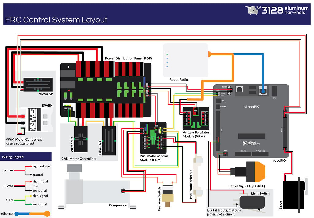
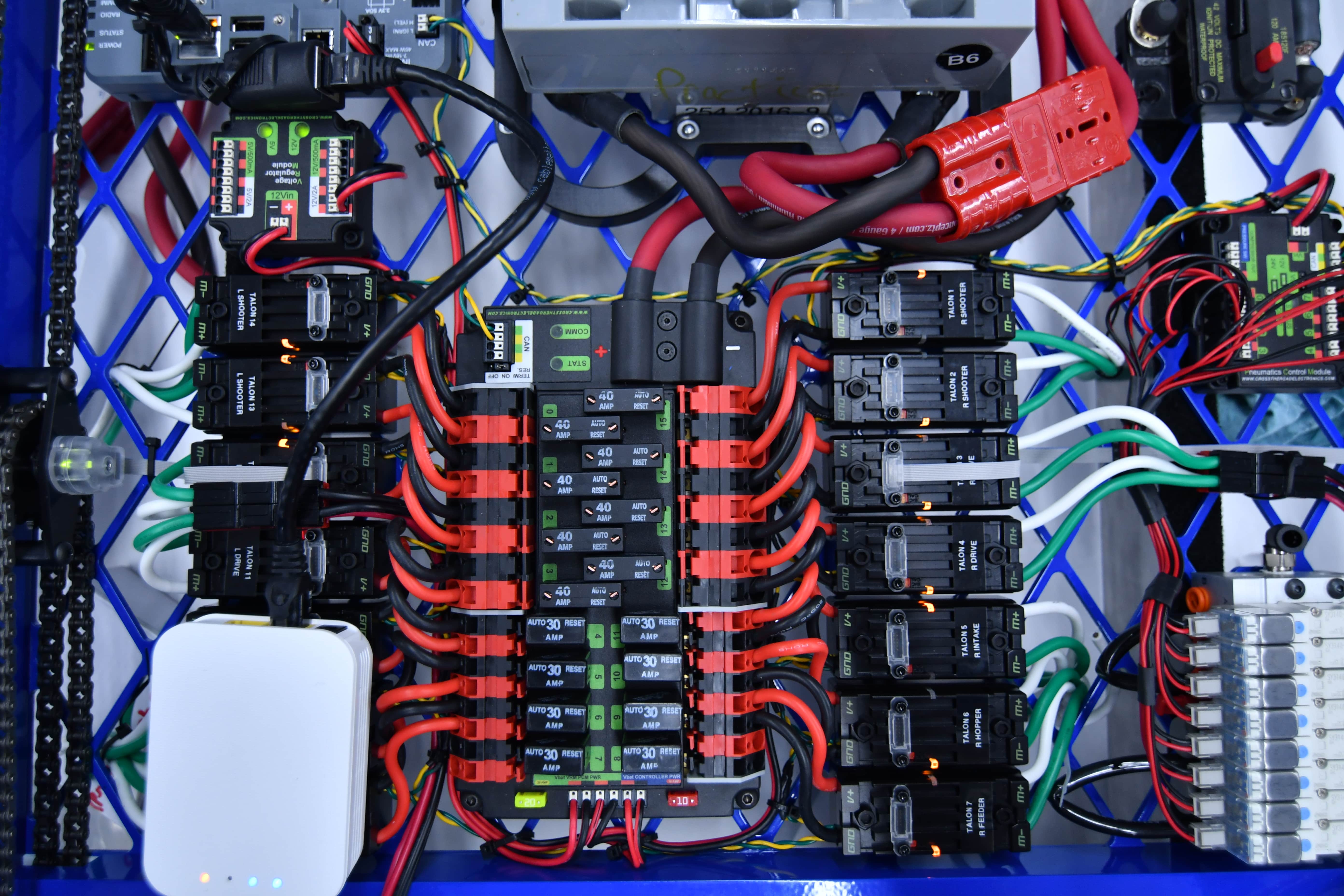
First Robotics Wiring Diagram. You may be able to know specifically once the assignments ought to be completed which makes it much easier for you personally to correctly manage your time. With this kind of an illustrative guide youll be capable of troubleshoot avoid and total your assignments with ease. Keep an eye out for other potential areas to provide redundancy when wiring and programming your robot. The Voltage Regulator Module VRM is an independent module that is powered by 12 volts.

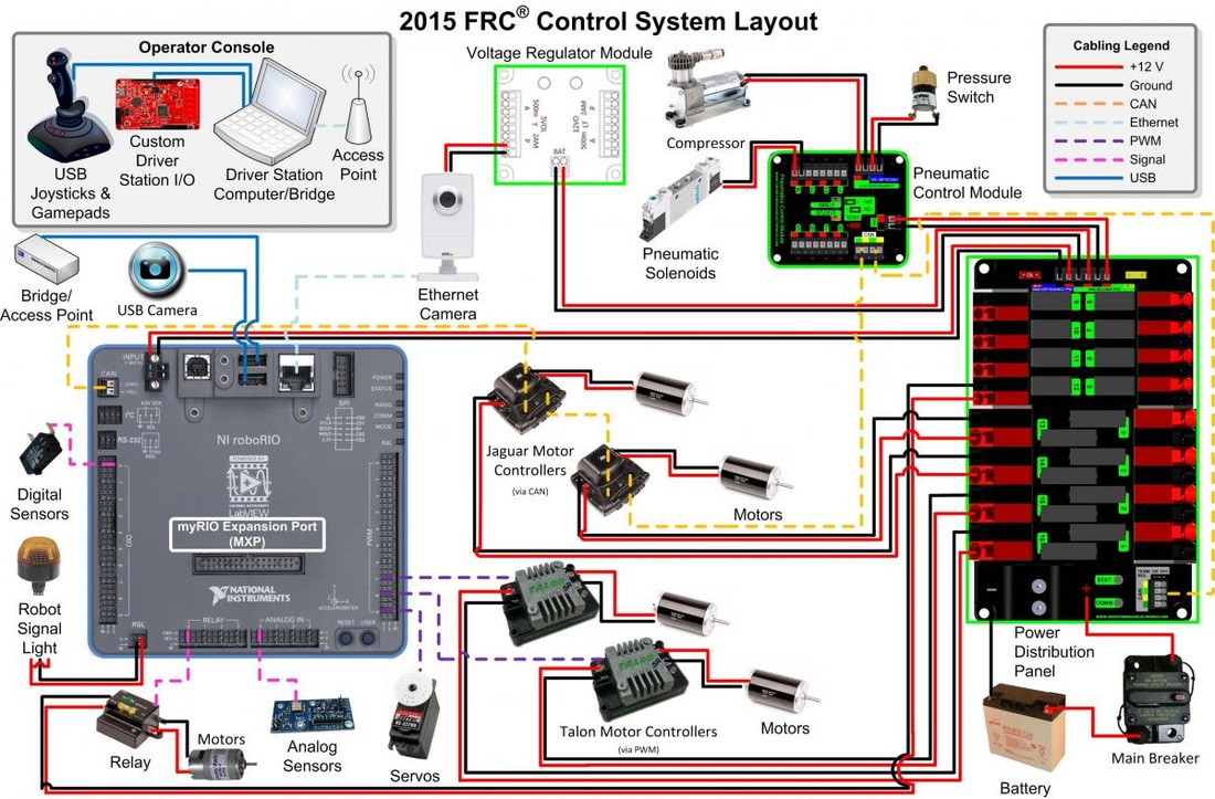
This photograph First Robotics Wiring Diagram Frc Control System 2016 Wiring within First Robotics Wiring Diagram previously mentioned is usually labelled using. The purpose of the VRM is to provide regulated power for the robot radio custom circuits and IP vision cameras. Introduction to Robot Wiring. If the main power leads are loose that tug can get all the way back to the crimp lugs attached to the 120 Amp Circuit Breaker or Power Distribution Panel PDP bend the lug and over time cause the lug end to break from fatigue. The Robot Signal Light Introduction. AM14U Drive System for the.
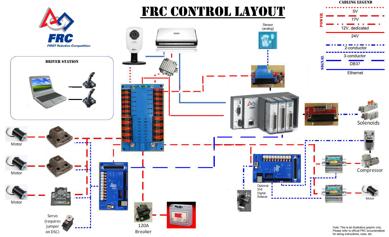
Team358 Robotic Eagles First Robotics Competition Frc Wiring Diagram.
The first purpose is to provide electrical power to the devices on a robot. 28 KB Victor 883 Users Manual 32 KB Victor 883 FET 221 KB 2003-2006 Radios. These diagrams are relatively simple to create and are useful for the following reasons. Here is a picture gallery about first robotics wiring diagram complete with the description of the image please find the image you need. National Instruments is the manufacturer and donator of the Compact RIO cRIO hardwarefirmware that forms the backbone of the FIRST Robotics Competition control system beginning in 2009. Connect the PWM Y-cables to the PWM ports on the roboRIO.
 Source: pinterest.com
Connect La to S and N to Ground on the roboRIO. The purpose of the VRM is to provide regulated power for the robot radio custom circuits and IP vision cameras. Basics Of Drawing Schematics In Solidworks Electrical 2d Exercise 03 2021 Solidworks Electrical Help Solidworks Electrical Manual Pdf Jobs Ecityworks 2 Solidworks Electrical Schematic. The Robot Signal Light Introduction. A general term for a component used to turn electrical energy into rotational kinetic energy.
 Source: team358.org
Team358 Robotic Eagles First Robotics Competition Frc Wiring Diagram. Connect the PWM Y-cables to the PWM ports on the roboRIO. And They become a valuable reference when included in the Engineering Notebook. A loose robot-side battery connector the large Anderson SB can allow the main power leads to be tugged when the battery is replaced. AM14U Drive System for the.
 Source: pinterest.com
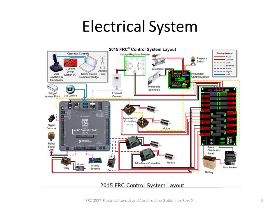
The second purpose is to provide a communication network for the many devices that make up a robots control system. These diagrams are relatively simple to create and are useful for the following reasons. Diagram first robotics. A separate wire acts as a jumper between La and Lb. And They become a valuable reference when included in the Engineering Notebook.
 Source: chiefdelphi.com
Connect La to S and N to Ground on the roboRIO. Component used to store code and send commands to components. Using the 716 box end secure the wire to the AUX side of the 120A main breaker. This information is contained within the FIRST Robotics 2015 SOLIDWORKS Electrical Environment. Acrobat the Adobe PDF logo.
 Source: team254.com
Control System Hardware Components. The first purpose is to provide electrical power to the devices on a robot. Full 3648x2736 medium 235x150 large 640x480 frc wiring diagram Youll need an extensive skilled and easy to know Wiring Diagram. A separate wire acts as a jumper between La and Lb. 2014 FIRST Robotics Competition.
 Source: slideplayer.com
You may be able to know specifically once the assignments ought to be completed which makes it much easier for you personally to correctly manage your time. Connect 1 PWM Y-cable to the 2 PWM cables for the controllers controlling each side of the robot. Submitted through Tops Stars Team from November 5 2013. PCM Power and Control Wiring The first PCM on your robot can be wired from the PDP VRMPCM connectors on the end of the PDP. If the main power leads are loose that tug can get all the way back to the crimp lugs attached to the 120 Amp Circuit Breaker or Power Distribution Panel PDP bend the lug and over time cause the lug end to break from fatigue.
 Source: peerfba.fannyparrucchieri.it
The Robot Signal Light Introduction. Full 3648x2736 medium 235x150 large 640x480 frc wiring diagram Youll need an extensive skilled and easy to know Wiring Diagram. Using the 716 box end secure the wire to the AUX side of the 120A main breaker. Three types of cRIO module breakout boards-Digital Analog Solenoid. A general term for a component used to turn electrical energy into rotational kinetic energy.
 Source: chiefdelphi.com
You may be able to know specifically once the assignments ought to be completed which makes it much easier for you personally to correctly manage your time. Using the 5mm secure the other end to the PDP positive terminal. Connect La to S and N to Ground on the roboRIO. How to Use 2 Joysticks on a single OI Port 118 KB Victor Legacy Victor 883 Installation Info. The first purpose is to provide electrical power to the devices on a robot.

Acrobat the Adobe PDF logo. First Robotics Wiring Diagram Boulderrail intended for First Robotics Wiring Diagram image size 501 X 501 px and to view image details please click the image. Component used to store code and send commands to components. The PCM is connected to the roboRIO via CAN and can be placed anywhere in the middle of the CAN chain or on the end with a custom terminator. Full 3648x2736 medium 235x150 large 640x480 frc wiring diagram Youll need an extensive skilled and easy to know Wiring Diagram.
 Source: yeoryia-aslanidou.com
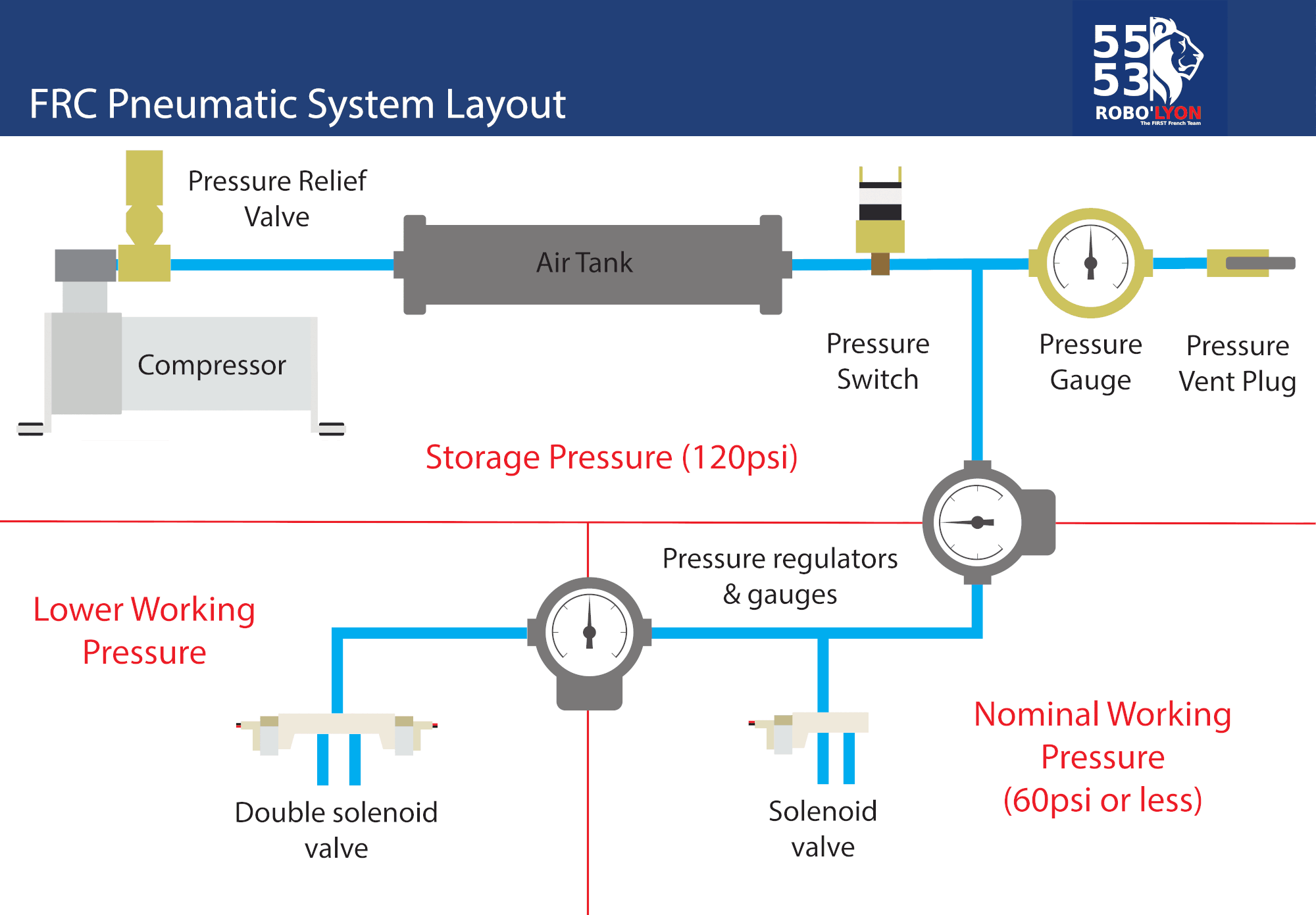
Air Tank A plastic air tank is available in FIRST Choice and the rookie Kickoff Kit from Clippard Instruments. Contents Page AndyMark Background 2 System Overview 2 Wheel Assembly BOM 3 Toughbox Mini Overview and BOM 4-5 AM14U Chassis BOM 6 AM14U Chassis Frame Diagrams and Cut Lines 7 4 HiGrip Wheel and Pulley Assembly Instructions 8 Toughbox Mini and AM14U Chassis Assembly. Measure out the length of wire required to reach the positive terminal of the PDP. The Robot Signal Light Introduction. Using the 5mm secure the other end to the PDP positive terminal.
 Source: create.arduino.cc
The module has multiple regulated 12V and 5V outputs. Component used to wirelessly communicate with the robot. PCM Power and Control Wiring The first PCM on your robot can be wired from the PDP VRMPCM connectors on the end of the PDP. If any Solenoid Valve object is opened LabVIEW or constructed CJava in your code the PCM compressor control will be automatically enabled. Team358 Robotic Eagles First Robotics Competition Frc Wiring Diagram.
 Source: pinterest.com
The wiring of a robot serves two primary purposes. Introduction to Robot Wiring. The purpose of the VRM is to provide regulated power for the robot radio custom circuits and IP vision cameras. A general term for a component used to turn electrical energy into rotational kinetic energy. If any Solenoid Valve object is opened LabVIEW or constructed CJava in your code the PCM compressor control will be automatically enabled.

Using the 716 box end secure the wire to the AUX side of the 120A main breaker. Keep an eye out for other potential areas to provide redundancy when wiring and programming your robot. The primary example of this is wiring the barrel connector to the radio in addition to the provided PoE connection. The module has multiple regulated 12V and 5V outputs. First Robotics Wiring Diagram Boulderrail intended for First Robotics Wiring Diagram.
Contents Page AndyMark Background 2 System Overview 2 Wheel Assembly BOM 3 Toughbox Mini Overview and BOM 4-5 AM14U Chassis BOM 6 AM14U Chassis Frame Diagrams and Cut Lines 7 4 HiGrip Wheel and Pulley Assembly Instructions 8 Toughbox Mini and AM14U Chassis Assembly. Contents Page AndyMark Background 2 System Overview 2 Wheel Assembly BOM 3 Toughbox Mini Overview and BOM 4-5 AM14U Chassis BOM 6 AM14U Chassis Frame Diagrams and Cut Lines 7 4 HiGrip Wheel and Pulley Assembly Instructions 8 Toughbox Mini and AM14U Chassis Assembly. The primary example of this is wiring the barrel connector to the radio in addition to the provided PoE connection. Schematic Dassault Systèmes SOLIDWORKS Corporation 175. Measure out the length of wire required to reach the positive terminal of the PDP.

Robotic Assembly Of Automotive Wire Harnesses 2014 07 01 First Robotics Wiring Diagram Wiring Schematic Diagram 1d1c8c Toy Robot Wiring Diagram Wiring Resources Mearm Arduino Servo Motor Wire Schematic Arduino Servo Arduino Hobby Robot Building Light Following Arduino Robot Using Photoresistors Learn Robotics. Using the 716 box end secure the wire to the AUX side of the 120A main breaker. How to Use 2 Joysticks on a single OI Port 118 KB Victor Legacy Victor 883 Installation Info. Air Tank A plastic air tank is available in FIRST Choice and the rookie Kickoff Kit from Clippard Instruments. Using the 5mm secure the other end to the PDP positive terminal.

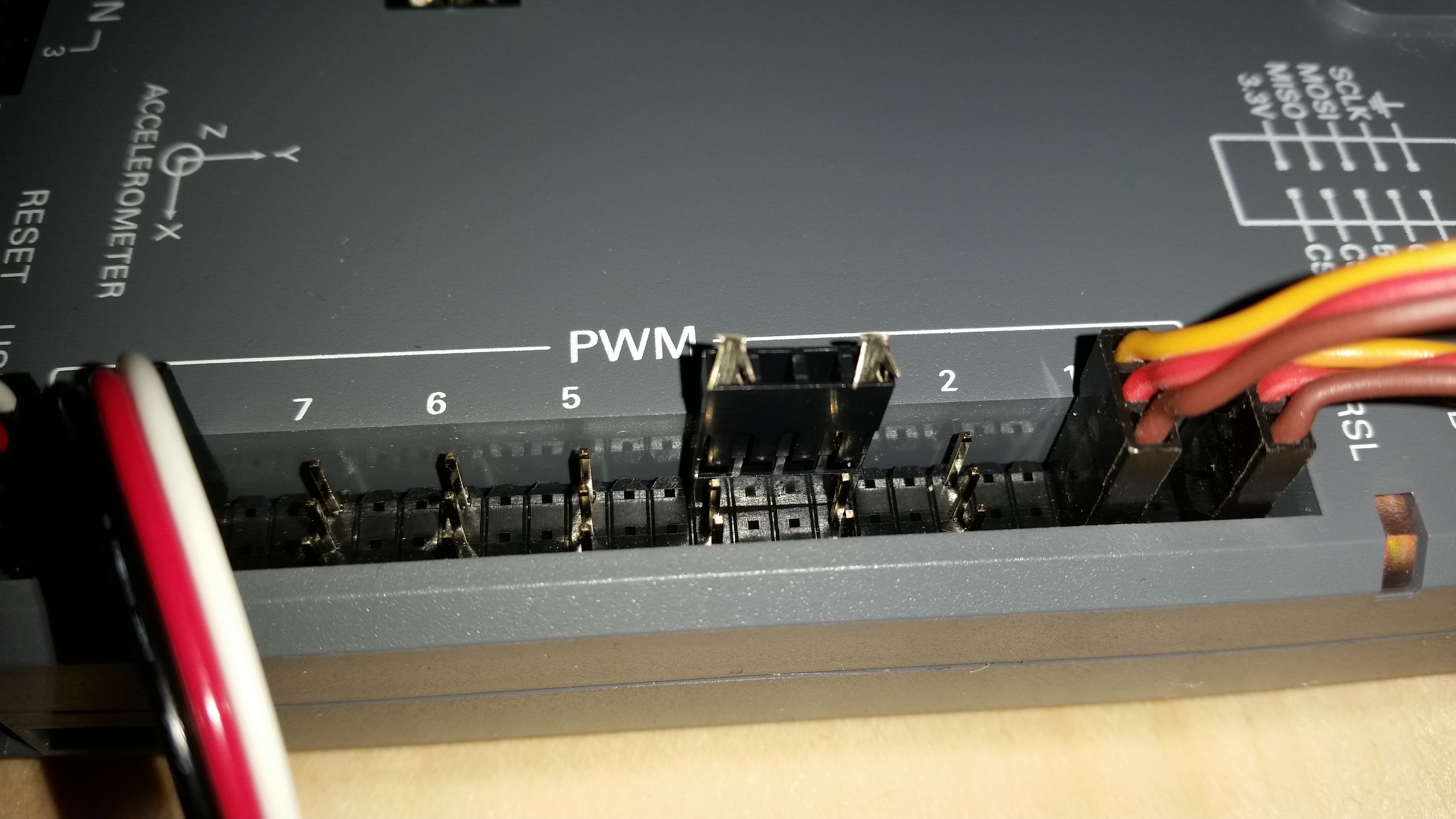
First Robotics Wiring Diagram Boulderrail intended for First Robotics Wiring Diagram. The PCM is connected to the roboRIO via CAN and can be placed anywhere in the middle of the CAN chain or on the end with a custom terminator. The Robot Signal Light RSL is mandatory during competition and acts as a signal to whether the robot is connected to the FCS in teleop mode etc. The brown wire on the Y-cable should match the black wire on the PWM cable. If the main power leads are loose that tug can get all the way back to the crimp lugs attached to the 120 Amp Circuit Breaker or Power Distribution Panel PDP bend the lug and over time cause the lug end to break from fatigue.
 Source: pinterest.com
A separate wire acts as a jumper between La and Lb. FIRST published this wiring diagram to take advantage of the normally unused analog inputs on each 2000-2008 OI joystick port to hook 2 joysticks to a single port. This ensures that if one of the cables becomes damaged or dislodged the other will maintain power to the radio. A separate wire acts as a jumper between La and Lb. This photograph First Robotics Wiring Diagram Frc Control System 2016 Wiring within First Robotics Wiring Diagram previously mentioned is usually labelled using.
 Source: forum.fritzing.org
Connect 1 PWM Y-cable to the 2 PWM cables for the controllers controlling each side of the robot. Introduction to Robot Wiring. This photograph First Robotics Wiring Diagram Frc Control System 2016 Wiring within First Robotics Wiring Diagram previously mentioned is usually labelled using. Open 03 Wiring line diagram from the project drawing list. The second purpose is to provide a communication network for the many devices that make up a robots control system.
This site is an open community for users to do submittion their favorite wallpapers on the internet, all images or pictures in this website are for personal wallpaper use only, it is stricly prohibited to use this wallpaper for commercial purposes, if you are the author and find this image is shared without your permission, please kindly raise a DMCA report to Us.
If you find this site value, please support us by sharing this posts to your own social media accounts like Facebook, Instagram and so on or you can also bookmark this blog page with the title first robotics wiring diagram by using Ctrl + D for devices a laptop with a Windows operating system or Command + D for laptops with an Apple operating system. If you use a smartphone, you can also use the drawer menu of the browser you are using. Whether it’s a Windows, Mac, iOS or Android operating system, you will still be able to bookmark this website.