Frequency mixer circuit diagram
Home » Wallpapers » Frequency mixer circuit diagramYour Frequency mixer circuit diagram images are available in this site. Frequency mixer circuit diagram are a topic that is being searched for and liked by netizens today. You can Get the Frequency mixer circuit diagram files here. Get all royalty-free images.
If you’re looking for frequency mixer circuit diagram pictures information linked to the frequency mixer circuit diagram keyword, you have come to the ideal blog. Our site frequently provides you with suggestions for downloading the highest quality video and image content, please kindly search and find more enlightening video articles and graphics that fit your interests.
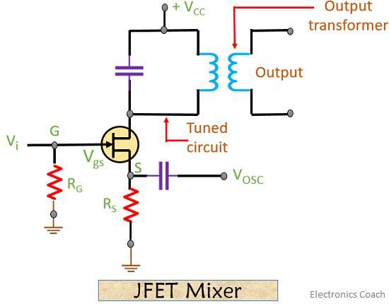
Frequency Mixer Circuit Diagram. R3 47K - 14W Resistor. Self-excited mixer The mixer circuits that uses FET or MOSFET are known as the self-excited mixer. Draw a block diagram of an FM receiver showing the frequency and type of signal. However some valves vacuum tube types had two separate sections in them like the 6U8 ECF82 type and others.
 Chapter 18 Mixer Rf Circuit Design 2nd Edition Book From oreilly.com
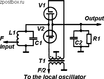
This process is known as superheterodyning and is what gives the receiver its name. Ble-balanced mixer in an 8-pin DIP as shown in Fig. Each input channel of audio mixer is connected the inverting terminal of op amp. The mixer takes signals that have been filtered by the input network and converts them to an intermediate frequency of 1700 kHz by combining them with a signal from the local oscillator. Some used a single valve section - a heptode tube or valve could act as a single oscillator frequency changer circuit. RF mixer circuit symbol.
Mixers found in common AM receivers output the sum the difference of the LO and RFs frequencies.
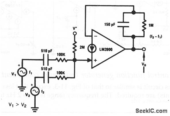
RF mixer circuit symbol. Some of these single-ended mixer can also take advantage of a somewhat lower level of LO power needed to drive the single-. 2 a block diagram of the IC. RF mixer circuit symbol. However some valves vacuum tube types had two separate sections in them like the 6U8 ECF82 type and others. To make audio mixer circuit we need amplifier stage and here LM3900 IC is used as amplifier stage.

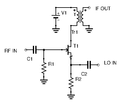
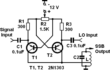
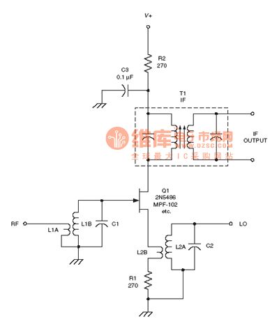
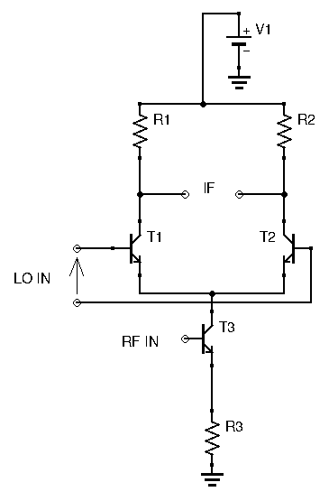
Are the radio frequency RF input the local oscillator LO input and the intermediate frequency IF output. The main component in this circuit is lm3900 quad operational amplifier. In electronics a mixer or frequency mixer is a nonlinear electrical circuit that creates new frequencies from two signals applied to it. The frequency of the local oscillator is set so either the sum or the difference of the RF signals frequency and the LOs frequency is equal to the IF used in the receiver usually around 455 kHz. Szekit Member level 5.
 Source: researchgate.net
Are the radio frequency RF input the local oscillator LO input and the intermediate frequency IF output. The Mixing Process A mixer takes an RF input signal at a frequency fRF mixes it with a LO signal at a frequency fLO and produces an IF output signal that consists of the sum and difference frequencies fRF fLO. The third block is the mixer the RF signal and the LO signal is fed to the mixer to produce the desired IF. R1 22K - 14W Resistor. Types of Frequency Mixer.
 Source: modernhamguy.com
Ble-balanced mixer in an 8-pin DIP as shown in Fig. Self-excited mixer The mixer circuits that uses FET or MOSFET are known as the self-excited mixer. Draw a block diagram of an FM receiver showing the frequency and type of signal. Trace the signal flow through FM stereo and SCA decoder circuits. The third block is the mixer the RF signal and the LO signal is fed to the mixer to produce the desired IF.
 Source: zpostbox.ru
The Mixing Process A mixer takes an RF input signal at a frequency fRF mixes it with a LO signal at a frequency fLO and produces an IF output signal that consists of the sum and difference frequencies fRF fLO. Using the values given on the diagram the circuit oscillates at 46 MHz. It is typically used when an RF mixer module is used. Draw a block diagram of an FM receiver showing the frequency and type of signal. R1 22K - 14W Resistor.
 Source: seekic.com
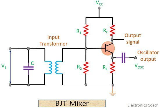
There are highlow-sensitivity switchable inputs for each input channel and each channel used low noise and high gain transistor of BC550C. The output of each op amp is given to single output. IIP3 dBm LO dBm 9dB 20LOGG MAX Where G MAX. Its amplifier component can then be used as the oscillator by adding an LC network to it L1C1. The local oscillator signal is V OSC V m2 sin ω H t.
 Source: oreilly.com
And the mixer to 500 MHz. Some used a single valve section - a heptode tube or valve could act as a single oscillator frequency changer circuit. The circuit works according to a simple principle. The main component in this circuit is lm3900 quad operational amplifier. In passive FET mixers the gate input which is driven by the LO looks like a high-Q capacitor.
 Source: analog.intgckts.com
The third block is the mixer the RF signal and the LO signal is fed to the mixer to produce the desired IF. So far we have an audio-frequency AF amplifier and a VFO. Multi Channel Audio Mixer using LM3900 Circuit Design. This prevents most of. The audio mixing circuit alone is a very simple summing amplifier made with an op-amp.
 Source: electronicscoach.com
This is widely used in the circuit schematics for many RF circuit designs. To make audio mixer circuit we need amplifier stage and here LM3900 IC is used as amplifier stage. This circuit symbol indicates the multiplication aspect of the mixer. This circuit is only found in very low-cost circuits with the isolation between ports being supplied by bandpass and lowpass filters that are separated in frequency. The circuit works according to a simple principle.
 Source: commons.wikimedia.org
Mixer as frequency doubler 100MHz is a relative high frequency. R2 22K - 14W Resistor. In electronics a mixer or frequency mixer is a nonlinear electrical circuit that creates new frequencies from two signals applied to it. To make audio mixer circuit we need amplifier stage and here LM3900 IC is used as amplifier stage. A music generator IC is used to produce high frequency musical sound which will be then mixed with the audio mixing circuit.
 Source: zpostbox.ru
The circuit works according to a simple principle. So far we have an audio-frequency AF amplifier and a VFO. This is the simple and low cost 3 channels mini audio mixer circuit diagram. The antenna to the mixer circuit. Schematic Diagram and Circuit Descriptions Page.
 Source: commons.wikimedia.org
The mixer takes signals that have been filtered by the input network and converts them to an intermediate frequency of 1700 kHz by combining them with a signal from the local oscillator. The NE602 was originally de- signed for VHF receiver front ends since the LO works up to 200 MHz. Using the values given on the diagram the circuit oscillates at 46 MHz. This process is known as superheterodyning and is what gives the receiver its name. IIP3 dBm LO dBm 9dB 20LOGG MAX Where G MAX.
 Source: modernhamguy.com
The audio mixing circuit alone is a very simple summing amplifier made with an op-amp. Sep 26 2006 3 S. RF mixer circuit symbol. So far we have an audio-frequency AF amplifier and a VFO. This simple circuit mixes two or more channels into one channel or stereo.
 Source: pinterest.com
The mixer circuit diagram is. Are the radio frequency RF input the local oscillator LO input and the intermediate frequency IF output. Frequency multiplier circuit diagram You need to specify your input frequency range. Draw a block diagram of an FM receiver showing the frequency and type of signal. 2 a block diagram of the IC.
 Source: seekic.com
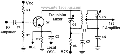
There are highlow-sensitivity switchable inputs for each input channel and each channel used low noise and high gain transistor of BC550C. BJT Mixer Lets have look at the circuit diagram of BJT mixer-Here the input signal is V i V m1 sin ω L t and. The mixer circuit diagram is. In electronics a mixer or frequency mixer is a nonlinear electrical circuit that creates new frequencies from two signals applied to it. Szekit Member level 5.
 Source: next.gr
The antenna to the mixer circuit. The antenna to the mixer circuit. This process is known as superheterodyning and is what gives the receiver its name. Schematic Diagram and Circuit Descriptions Page. The frequency of the local oscillator is set so either the sum or the difference of the RF signals frequency and the LOs frequency is equal to the IF used in the receiver usually around 455 kHz.
 Source: electronicscoach.com
Draw a block diagram of an FM receiver showing the frequency and type of signal. There are highlow-sensitivity switchable inputs for each input channel and each channel used low noise and high gain transistor of BC550C. 2 a block diagram of the IC. However some valves vacuum tube types had two separate sections in them like the 6U8 ECF82 type and others. Block Diagram of Audio Mixer Circuit.
 Source: electroschematics.com
This process is known as superheterodyning and is what gives the receiver its name. However some valves vacuum tube types had two separate sections in them like the 6U8 ECF82 type and others. However it has plenty of uses at lower frequen- cies as well and this article will ex- plore them. Mixer as frequency doubler 100MHz is a relative high frequency. The addition of a mixer board gives us a complete direct-conversion receiver for 80 m.
 Source: researchgate.net
This circuit will give only mixed audio output signal with minimum gain and you can use external amplifier to strengthen the Audio output signal. Its amplifier component can then be used as the oscillator by adding an LC network to it L1C1. Ble-balanced mixer in an 8-pin DIP as shown in Fig. Each input channel of audio mixer is connected the inverting terminal of op amp. 4 Channel Audio mixer Circuit diagram.
This site is an open community for users to share their favorite wallpapers on the internet, all images or pictures in this website are for personal wallpaper use only, it is stricly prohibited to use this wallpaper for commercial purposes, if you are the author and find this image is shared without your permission, please kindly raise a DMCA report to Us.
If you find this site convienient, please support us by sharing this posts to your preference social media accounts like Facebook, Instagram and so on or you can also bookmark this blog page with the title frequency mixer circuit diagram by using Ctrl + D for devices a laptop with a Windows operating system or Command + D for laptops with an Apple operating system. If you use a smartphone, you can also use the drawer menu of the browser you are using. Whether it’s a Windows, Mac, iOS or Android operating system, you will still be able to bookmark this website.