Gear terminology with diagram pdf
Home » Background » Gear terminology with diagram pdfYour Gear terminology with diagram pdf images are available in this site. Gear terminology with diagram pdf are a topic that is being searched for and liked by netizens now. You can Get the Gear terminology with diagram pdf files here. Get all royalty-free vectors.
If you’re looking for gear terminology with diagram pdf images information linked to the gear terminology with diagram pdf interest, you have come to the ideal blog. Our site always provides you with hints for seeking the highest quality video and image content, please kindly search and locate more enlightening video articles and graphics that fit your interests.
Gear Terminology With Diagram Pdf. These are typically spur gears as shown in diagram 1. The drive between the two gears can be represented by using plain cylinders or discs 1 and 2 having diameters equal to their pitch circles as shown in Figure 35. Basics 14 AOV Schematic with Block included Basics 15 Wiring or Connection Diagram. Accordingly some specifications may not be applicable for individual vehicles.
 Gear Classification Engineering Made Easy Mechanical Engineering Gears Mechanical Engineering Design From pinterest.com
Cam profile is the surface area of a cam where follower meets. The main disadvantage of the helical gear -. 23 Number of teeth. However parallel axes spur and helical gears are the main gears in automotive transmission. These are typically spur gears as shown in diagram 1. Name That Gear What type of worm gear set is this.
Gear drive center-to-center distances are restricted to specific dimensions for a given set of gears the center distances between two chained sprockets can vary anywhere from 50 to 300 or more of their pitch diameters.
The number of teeth for spur gears is given by where k 1f fll1 for full-d tht th08f tbt th d ldepth teeth 08 for stub teeth and φ pressure angle. The main disadvantage of the helical gear -. When gear sets are visualized as a pair of smooth contacting. The point of contact of the two pitch surfaces shell have velocity along the common tangent. Manufacturing of gears presents a demanding challenge for metallurgists in heat treatment for supervisors in machining and gear cutting and for quality engineers in keeping the quality to the required standards. Cam profile is the surface area of a cam where follower meets.
 Source: unacademy.com
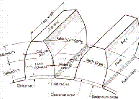
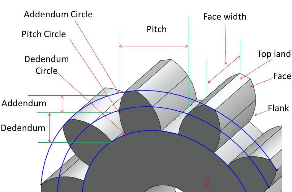
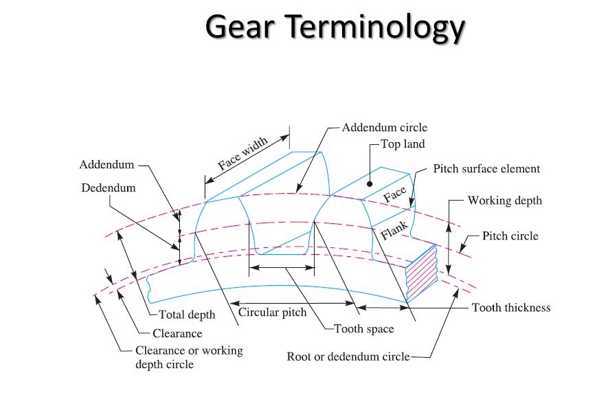
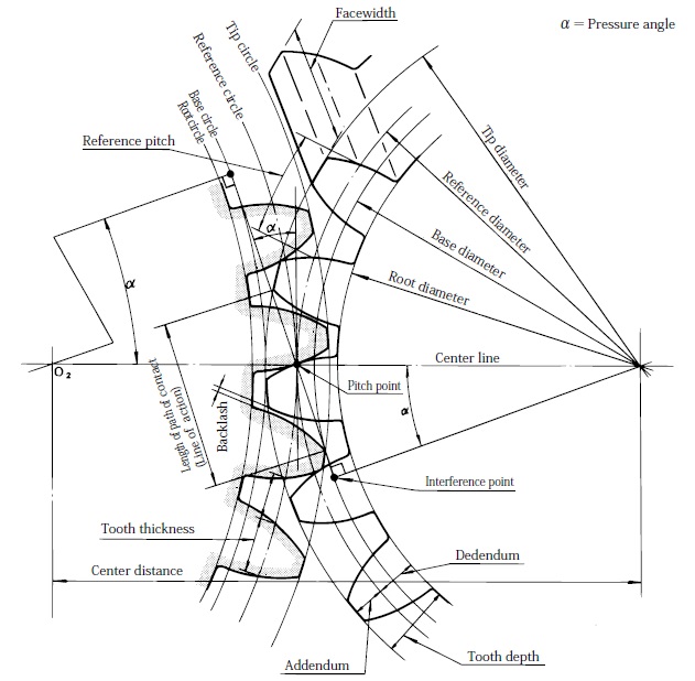
Basics 7 416 kV 3-Line Diagram. Gear Terminology AGMA American Gear Manufacturers Association ANSI American National Standards Institute Addendum ADD the radial or perpendicular distance between the pitch circle and the top of the teeth Alignment Accuracy of the alignment of shafts on which gears are mounted is a critical factor in their life and performance. It has no affect on the gear ratio. The teeth on the gears must all be the same size so if gear. The number of teeth of this gear is 10.
 Source: engineering.myindialist.com
Important Gear Terminology and Gear Nomenclature in Fig 22 Reference line. Spur gears and helical gears are parallel axes gears. Diametral Pitch DP The Diametral Pitch describes the gear tooth size. The point of contact of the two pitch surfaces shell have velocity along the common tangent. It has no affect on the gear ratio.
 Source: fliphtml5.com
A gear can be defined as a toothed wheel which when meshed with another toothed wheel with similar configura-tion will transmit rotation from one shaft to another. It has no affect on the gear ratio. The direction of rotation is reversed from one gear to another. A right section of the pitch surface. 2 In each section all specifications are listed including optional specifications.
 Source: mech4study.com
When gear sets are visualized as a pair of smooth contacting. However parallel axes spur and helical gears are the main gears in automotive transmission. 1 This manual consists of wiring harness diagrams installation locations of individual parts circuits diagrams and index. Basic Gear Terminology INVOLUTE Face Width is the length of the teeth in the axial direction. Depending upon the type and accuracy of motion desired the gears and the profiles of the gear teeth can be of almost any form.
 Source: youtube.com
Gears come in all shapes and sizes from square to circular. Kinematic Diagram A kinematic layout is a pictorial representation of gearbox describing the arrangement of gears. 1 Single-enveloping single threaded 2 Single-enveloping multi-threaded 3 Double enveloping single threaded worm gear 4 Double enveloping multi-. Gear Terminology AGMA American Gear Manufacturers Association ANSI American National Standards Institute Addendum ADD the radial or perpendicular distance between the pitch circle and the top of the teeth Alignment Accuracy of the alignment of shafts on which gears are mounted is a critical factor in their life and performance. May be determined as the volume of fluid pumped per.

62 GEAR TERMINOLOGY The gear terminology is explained below with reference to a spur gear which is a particular type of a gear. 62 GEAR TERMINOLOGY The gear terminology is explained below with reference to a spur gear which is a particular type of a gear. Important Gear Terminology and Gear Nomenclature in Fig 22 Reference line. The only function of the idler gear is to change the direction of rotation. Gears are classified into 3 categories.
 Source: howmechanismworks.com
Gears are classified into 3 categories. The surface of the imaginary rolling cylinder cone etc that the toothed gear may be considered to replace. Ray diagram A ray diagram is. Parallel axes gears intersecting axes gears and nonparallel and nonintersecting axes gears. GEARS Educational Systems 105 Webster St.
 Source: theengineerspost.com
Kinematic Diagram A kinematic layout is a pictorial representation of gearbox describing the arrangement of gears. These are typically spur gears as shown in diagram 1. 23 Number of teeth. Because there is no slip definite motion of gear 1 can be transmitted to gear 2 or vice-versa. It has no affect on the gear ratio.
 Source: researchgate.net
Gear terminology - pitch circle Addendum circle dedendum circle Clearance backlash full depth face width Diametral pitch module circular pitch pressure angle pitch angle. Revolution of the gears. Basics 13 Valve Limit Switch Legend. Name That Gear What type of worm gear set is this. Basics 9 416 kV Pump Schematic.
 Source: koreindustries.com
Nomenclature or Terminology of Cam. 23 Number of teeth. The point of contact of the two pitch surfaces shell have velocity along the common tangent. Basics 9 416 kV Pump Schematic. However parallel axes spur and helical gears are the main gears in automotive transmission.
 Source: authorstream.com
The only function of the idler gear is to change the direction of rotation. It may be calculated from the physical dimensions of the gears or it. The surface of the imaginary rolling cylinder cone etc that the toothed gear may be considered to replace. Gear Terminology AGMA American Gear Manufacturers Association ANSI American National Standards Institute Addendum ADD the radial or perpendicular distance between the pitch circle and the top of the teeth Alignment Accuracy of the alignment of shafts on which gears are mounted is a critical factor in their life and performance. Spur gears and helical gears are parallel axes gears.
 Source: khkgears.net
Ray diagram A ray diagram is. Basics 10 480 V Pump Schematic. Important Gear Terminology and Gear Nomenclature in Fig 22 Reference line. Describe the gear milling gear finishing gear shaving gear burnishing roll finishing of gears process explain the gear lapping and honing process and understand the grinding of a gear. Bevel gears are intersecting axes gears.
 Source: engineering.myindialist.com
The teeth on the gears must all be the same size so if gear. These gears are also easier to design to fit given centre distances because there are more parameters that can be rearranged. Basics 8 AOV Elementary Block Diagram. Basics 13 Valve Limit Switch Legend. Assembly tolerances are not as restrictive as those for gear drives.
 Source: pinterest.com
Manufacturing of gears presents a demanding challenge for metallurgists in heat treatment for supervisors in machining and gear cutting and for quality engineers in keeping the quality to the required standards. Gear drive center-to-center distances are restricted to specific dimensions for a given set of gears the center distances between two chained sprockets can vary anywhere from 50 to 300 or more of their pitch diameters. Describe the gear milling gear finishing gear shaving gear burnishing roll finishing of gears process explain the gear lapping and honing process and understand the grinding of a gear. Basics 14 AOV Schematic with Block included Basics 15 Wiring or Connection Diagram. The most common way to classify gears is by category type and by the orientation of axes.
 Source: researchgate.net
The only function of the idler gear is to change the direction of rotation. It has no affect on the gear ratio. Important Gear Terminology and Gear Nomenclature in Fig 22 Reference line. Basics 13 Valve Limit Switch Legend. The drive between the two gears can be represented by using plain cylinders or discs 1 and 2 having diameters equal to their pitch circles as shown in Figure 35.
 Source: researchgate.net
Helical gears are superior to spur gears in most applications especially where noise must be kept to a minimum or the pitch line speed is in excess of 10 ms. These are typically spur gears as shown in diagram 1. The number of teeth for spur gears is given by where k 1f fll1 for full-d tht th08f tbt th d ldepth teeth 08 for stub teeth and φ pressure angle. Section Basic contents Wiring harness configuration diagrams. The point of contact of the two pitch surfaces shell have velocity along the common tangent.
 Source: sciencedirect.com
Name That Gear What type of worm gear set is this. Cam profile is the surface area of a cam where follower meets. If the mating gear has more teeth than the pinion that is mG NGNP m is more than one then the smallest number of teeth on. Manufacturing of gears presents a demanding challenge for metallurgists in heat treatment for supervisors in machining and gear cutting and for quality engineers in keeping the quality to the required standards. 23 Number of teeth.
 Source: koreindustries.com
A right section of the pitch surface. A right section of the pitch surface. The only function of the idler gear is to change the direction of rotation. The number of teeth of this gear is 10. Basics 11 MOV Schematic with Block included Basics 12 12-208 VAC Panel Diagram.
This site is an open community for users to share their favorite wallpapers on the internet, all images or pictures in this website are for personal wallpaper use only, it is stricly prohibited to use this wallpaper for commercial purposes, if you are the author and find this image is shared without your permission, please kindly raise a DMCA report to Us.
If you find this site beneficial, please support us by sharing this posts to your own social media accounts like Facebook, Instagram and so on or you can also save this blog page with the title gear terminology with diagram pdf by using Ctrl + D for devices a laptop with a Windows operating system or Command + D for laptops with an Apple operating system. If you use a smartphone, you can also use the drawer menu of the browser you are using. Whether it’s a Windows, Mac, iOS or Android operating system, you will still be able to bookmark this website.