Goodman diagram ppt
Home » Wallpapers » Goodman diagram pptYour Goodman diagram ppt images are available in this site. Goodman diagram ppt are a topic that is being searched for and liked by netizens now. You can Get the Goodman diagram ppt files here. Find and Download all royalty-free vectors.
If you’re looking for goodman diagram ppt images information connected with to the goodman diagram ppt interest, you have pay a visit to the right site. Our website frequently provides you with suggestions for viewing the highest quality video and picture content, please kindly hunt and find more enlightening video articles and images that fit your interests.
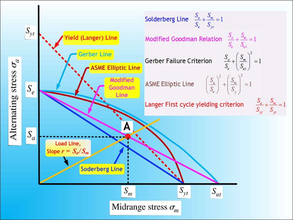
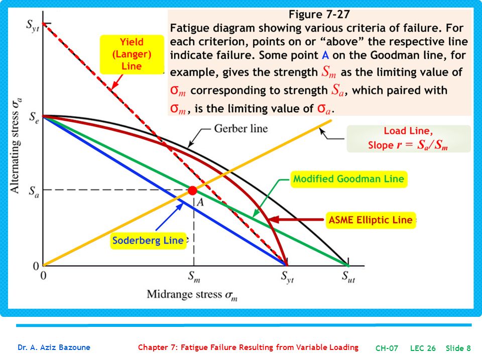
Goodman Diagram Ppt. Mathematically the three relationships can be expressed by. What is the factor of safety using Modified Goodmans equation if the part is subjected to moment load Mt varying between 2250000 N-mm and 1250000 N-mm in each cycle. Fatigue data presentation Goodman diagram An alternative method of presenting mean stress data is by using Heig-Soderberg diagram. G o o d m a n l i n e S u S n Note.
 Ppt Chapter 7 Powerpoint Presentation Free Download Id 674765 From slideserve.com
Stress-Life Diagram S-N Diagram The basis of the Stress-Life method is the Wohler S-N diagram shown schematically for two materials in Figure 1. This walks through a basic design example of a fluctuating axial stress on a steel pin at elevated non-zero mean stress using the modified Goodman diagram. If your point is below the Mod Goodman line the part should have unlimited life. On a blank PowerPoint slide navigate to the insert tab and click Shapes. Add one large rectangle for the body of your swimlane. σσσσ mean σσσ alt Note.
The Goodman Haigh Diagram For Infinite Life.
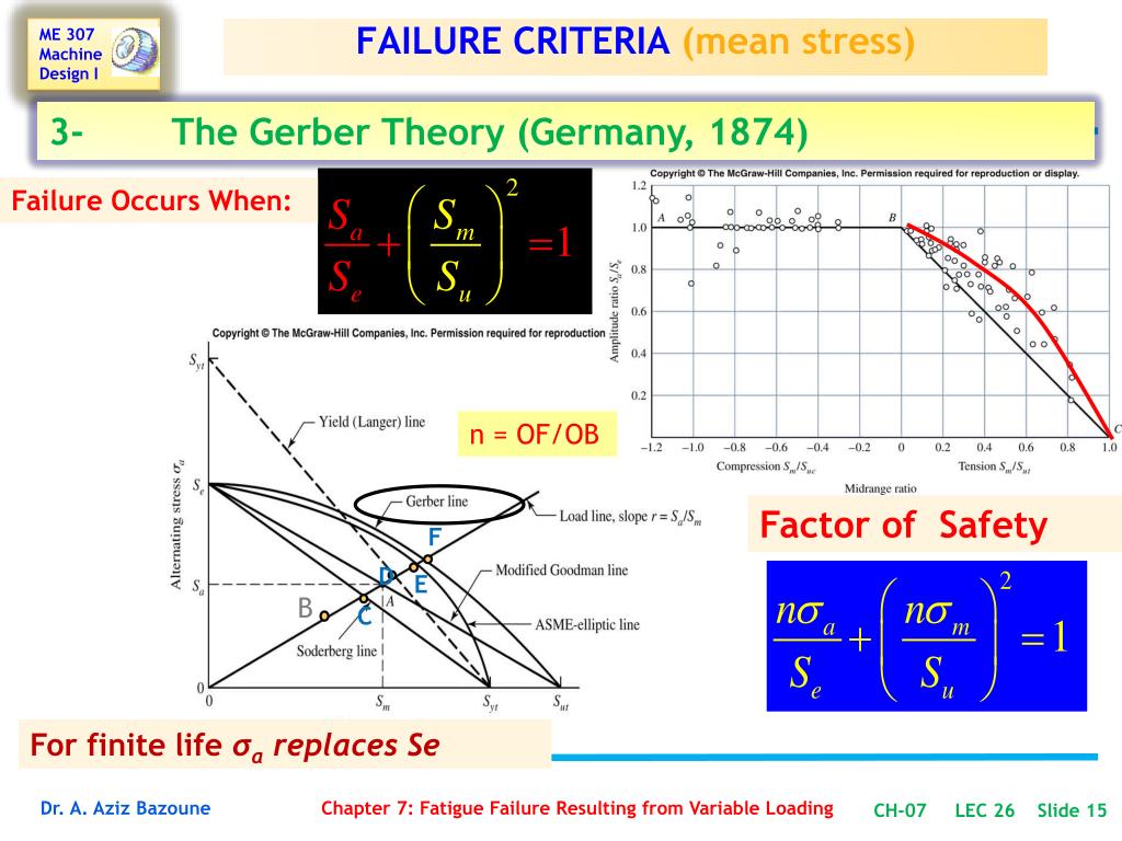
Add one large rectangle for the body of your swimlane. Stress-Life Diagram S-N Diagram The basis of the Stress-Life method is the Wohler S-N diagram shown schematically for two materials in Figure 1. Mathematically the three relationships can be expressed by. Fatigue Strength Juvinall p312 Fig. This is very different from the complete Modified Goodman Diagram that Hamrock details on P. The Effect of Mean Stress on FatigueThe Effect of Mean Stress on Fatigue Life Modified Goodman DiagramLife Modified Goodman Diagram Mean stress Alternating stress σm σa Sut Goodman line Sy Yield line Sy Se Safe zone C 18.
 Source: slideshare.net
Source: slideshare.net
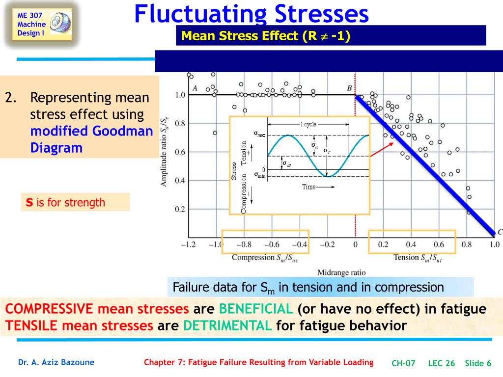
Goodman diagram drop in S e for rise in tensile S m. A plate made of steel 20C8 Sut440Nmm2. A Goodman diagram sometimes called a Haigh. There are numerous testing procedures to generate the required data for a proper S-N diagram. Monday March 28 2016 16 Materials select anMaterials select an ExampleExample Steel and Cast iron Aluminum alloys Plastics.
 Source: slideserve.com
Add one large rectangle for the body of your swimlane. The Goodman Haigh Diagram For Infinite Life. Goodman Diagram If f u2 m u2 What is the max and min that can be applied. 7 - Strain Life Approach This method is also called Critical Location CLA approach Local Stress-Strain E-N or Crack Initiation. This region is called Modified Goodman.
 Source: slideserve.com
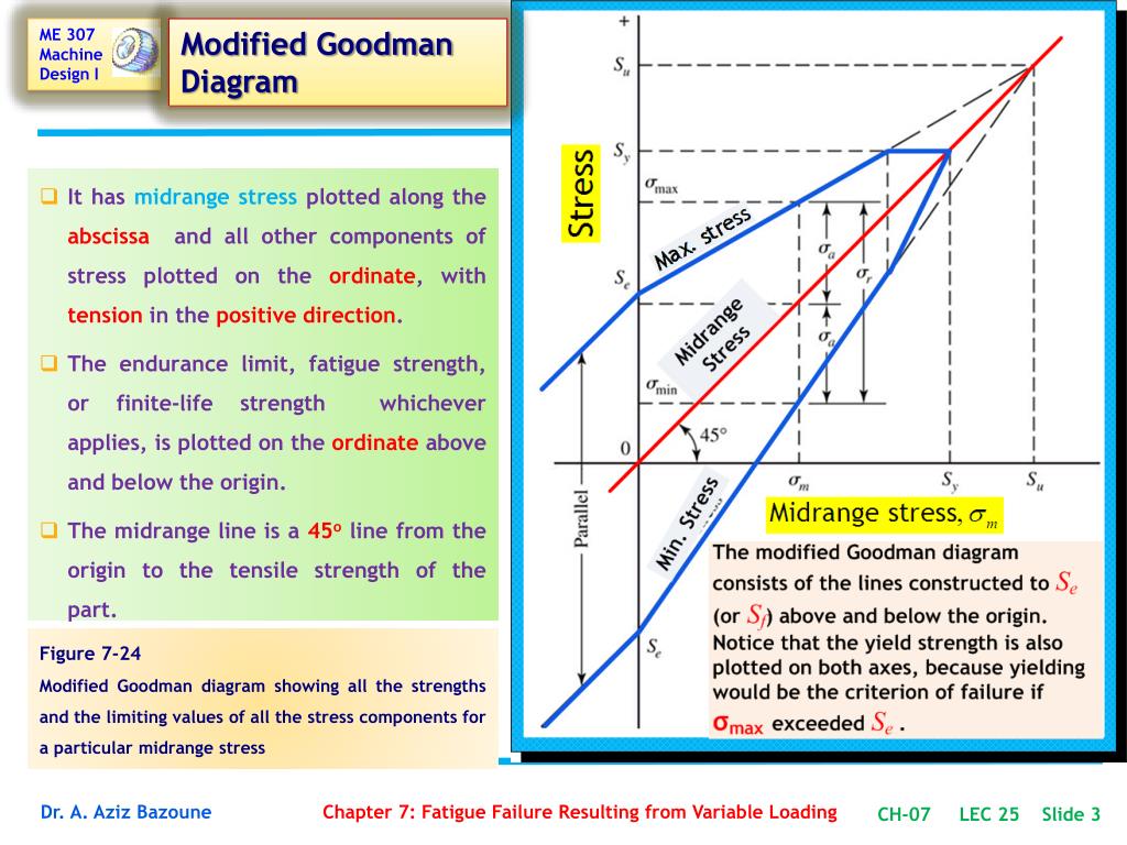
Modified Goodman Diagram Accounting for Yielding as a Failure Mode. The following equation summarizes the diagram. Number of Cycles S-N Diagram Miners Rule Damage from variable loadings is related to the life consumed by number of cycles at each particular STRESS RANGE. Our new CrystalGraphics Chart and Diagram Slides for PowerPoint is a collection of over 1000 impressively designed data-driven chart and editable diagram s guaranteed to impress any audience. 7 - Strain Life Approach This method is also called Critical Location CLA approach Local Stress-Strain E-N or Crack Initiation.
 Source: youtube.com
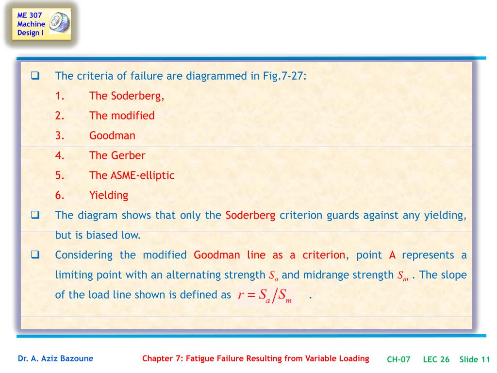
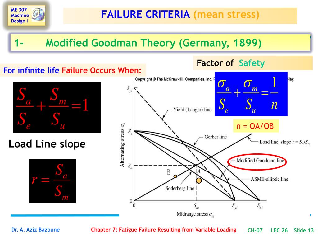
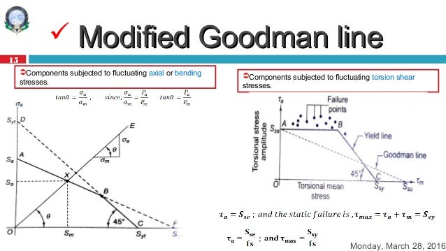
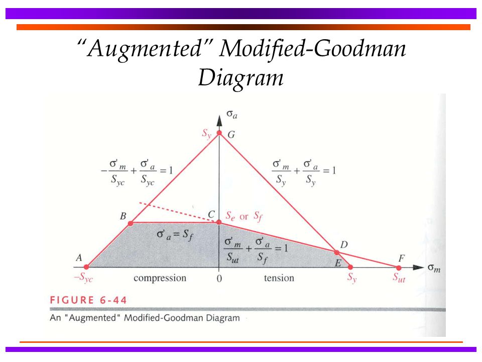
Fed17 Magazine Spring Software. Our new CrystalGraphics Chart and Diagram Slides for PowerPoint is a collection of over 1000 impressively designed data-driven chart and editable diagram s guaranteed to impress any audience. The Goodman line is modified by the fusion of yield lineDC and the Goodman line AF Yield line is made from the coordinates S ytS yt and the Goodman line is made from the coordinates S utS e B is the point of intersection of the two lines. Fatigue Strength Juvinall p312 Fig. Add one large rectangle for the body of your swimlane.
 Source: slideserve.com
Add one large rectangle for the body of your swimlane. This interpretation allows you to predict the maximum allowable alternating stress for a given mean stress. The stress range diagram defined above is the Goodman diagram for fiberglass sucker rods and is used for the same purposes as the modified Goodman diagram for steel rods. G o o d m a n l i n e S u S n Note. Goodman diagram endurance limit as a function of mean stress.
 Source: slideserve.com
Stress-Life Diagram S-N Diagram The basis of the Stress-Life method is the Wohler S-N diagram shown schematically for two materials in Figure 1. Alternating stress amplitude σ a. Our new CrystalGraphics Chart and Diagram Slides for PowerPoint is a collection of over 1000 impressively designed data-driven chart and editable diagram s guaranteed to impress any audience. The geometric stress concentration factor at the base of the radius is K 18The part is. It can be observed that an increase in temperature or in cycle.
 Source: slideserve.com
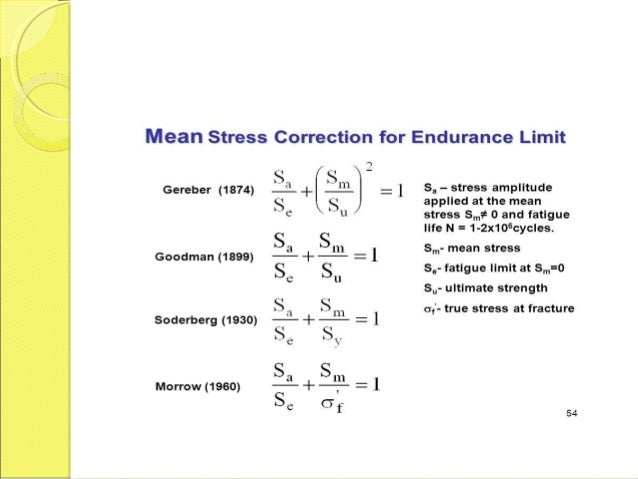
X1 for Goodman line x2 for the Gerber parabola. It can be observed that an increase in temperature or in cycle. Follow these steps to make a swimlane diagram in PowerPoint or skip to the next section to learn how to use Lucidchart. The Effect of Mean Stress on FatigueThe Effect of Mean Stress on Fatigue Life Modified Goodman DiagramLife Modified Goodman Diagram Mean stress Alternating stress σm σa Sut Goodman line Sy Yield line Sy Se Safe zone C 18. Goodman diagram endurance limit as a function of mean stress.
 Source: slideserve.com
If your point is below the Mod Goodman line the part should have unlimited life. If the component design is based on yield rather than ultimate strength as most are then the even more conservative Soderberg relationship can be used. Design for Cyclic Loading 6 of 7 Example 2. The Goodman Haigh Diagram For Infinite Life. The geometric stress concentration factor at the base of the radius is K 18The part is.
 Source: slideplayer.com
As fatigue strength S a. X1 for Goodman line x2 for the Gerber parabola. Example on reversed stressExample on reversed stress 1. Mean stress σ m as mid-range strength S m. As fatigue strength S a.
 Source: slideshare.net
G o o d m a n l i n e S u S n Note. The summation of life consumed at each stress range must be less than 1 to avoid failure. Stress-Life Diagram S-N Diagram The basis of the Stress-Life method is the Wohler S-N diagram shown schematically for two materials in Figure 1. Brittle materials are usually on Goodman line. Goodman diagram ppt diagram proace wiring diagram electrical connector trunk car swim lane diagram in ppt ex le swimming contributors circuit drawings and wiring diagrams mytrainingbc ca electrical wiring diagrams for dummies beautiful floor electrical schematics ppt wordpress com brushless alternator schematic ppt wordpress com industrial.
 Source: slideshare.net
Design for Cyclic Loading 6 of 7 Example 2. What is the factor of safety using Modified Goodmans equation if the part is subjected to moment load Mt varying between 2250000 N-mm and 1250000 N-mm in each cycle. This interpretation allows you to predict the maximum allowable alternating stress for a given mean stress. Chart and Diagram Slides for PowerPoint - Beautifully designed chart and diagram s for PowerPoint with visually stunning graphics and animation effects. Goodman Diagram for Fatigue.
 Source: slideshare.net
The Goodman line is modified by the fusion of yield lineDC and the Goodman line AF Yield line is made from the coordinates S ytS yt and the Goodman line is made from the coordinates S utS e B is the point of intersection of the two lines. There are numerous testing procedures to generate the required data for a proper S-N diagram. The Goodman line is modified by the fusion of yield lineDC and the Goodman line AF Yield line is made from the coordinates S ytS yt and the Goodman line is made from the coordinates S utS e B is the point of intersection of the two lines. Fed17 Magazine Spring Software. Goodman diagram drop in S e for rise in tensile S m.
 Source: slideserve.com
X1 for Goodman line x2 for the Gerber parabola. We will not use that version it is pretty confusing. The geometric stress concentration factor at the base of the radius is K 18The part is. Fatigue Limit Diagram According To Haigh And Smith Tec Science. Mean stress σ m as mid-range strength S m.
 Source: slideserve.com
Chavan In materials science and fatigue the Goodman relation is an equation used to quantify the interaction of mean and alternating stresses on the fatigue life of a material. Our new CrystalGraphics Chart and Diagram Slides for PowerPoint is a collection of over 1000 impressively designed data-driven chart and editable diagram s guaranteed to impress any audience. This walks through a basic design example of a fluctuating axial stress on a steel pin at elevated non-zero mean stress using the modified Goodman diagram. It can be observed that an increase in temperature or in cycle. The S-N diagram plots nominal stress amplitude S versus cycles to failure N.
 Source: slideplayer.com
Goodman diagram ppt diagram proace wiring diagram electrical connector trunk car swim lane diagram in ppt ex le swimming contributors circuit drawings and wiring diagrams mytrainingbc ca electrical wiring diagrams for dummies beautiful floor electrical schematics ppt wordpress com brushless alternator schematic ppt wordpress com industrial. Psi at a temperature of 160 F. It can be observed that an increase in temperature or in cycle. The Effect of Mean Stress on FatigueThe Effect of Mean Stress on Fatigue Life Modified Goodman DiagramLife Modified Goodman Diagram Mean stress Alternating stress σm σa Sut Goodman line Sy Yield line Sy Se Safe zone C 18. A Goodman diagram sometimes called a Haigh.
 Source: slideshare.net
The stress range diagram defined above is the Goodman diagram for fiberglass sucker rods and is used for the same purposes as the modified Goodman diagram for steel rods. Brittle materials are usually on Goodman line. The paper will begin with a working definition of fatigue and a brief discussion of fatigue characteristics. 7 - Strain Life Approach This method is also called Critical Location CLA approach Local Stress-Strain E-N or Crack Initiation. G o o d m a n l i n e S u S n Note.
 Source: slideplayer.com
Chart and Diagram Slides for PowerPoint - Beautifully designed chart and diagram s for PowerPoint with visually stunning graphics and animation effects. Smith Goodman Diagram Fatigue Written By JupiterZ Tuesday September 29 2020 Add Comment Edit. If the component design is based on yield rather than ultimate strength as most are then the even more conservative Soderberg relationship can be used. This region is called Modified Goodman. Monday March 28 2016 16 Materials select anMaterials select an ExampleExample Steel and Cast iron Aluminum alloys Plastics.
 Source: slideplayer.com
The S-N diagram plots nominal stress amplitude S versus cycles to failure N. This is very different from the complete Modified Goodman Diagram that Hamrock details on P. Mean stress σ m as mid-range strength S m. Components subjected to fluctuating torsion shear stresses. The Goodman line is modified by the fusion of yield lineDC and the Goodman line AF Yield line is made from the coordinates S ytS yt and the Goodman line is made from the coordinates S utS e B is the point of intersection of the two lines.
This site is an open community for users to submit their favorite wallpapers on the internet, all images or pictures in this website are for personal wallpaper use only, it is stricly prohibited to use this wallpaper for commercial purposes, if you are the author and find this image is shared without your permission, please kindly raise a DMCA report to Us.
If you find this site convienient, please support us by sharing this posts to your favorite social media accounts like Facebook, Instagram and so on or you can also bookmark this blog page with the title goodman diagram ppt by using Ctrl + D for devices a laptop with a Windows operating system or Command + D for laptops with an Apple operating system. If you use a smartphone, you can also use the drawer menu of the browser you are using. Whether it’s a Windows, Mac, iOS or Android operating system, you will still be able to bookmark this website.