Heat pump ts diagram
Home » Background » Heat pump ts diagramYour Heat pump ts diagram images are available. Heat pump ts diagram are a topic that is being searched for and liked by netizens today. You can Find and Download the Heat pump ts diagram files here. Find and Download all free vectors.
If you’re looking for heat pump ts diagram images information linked to the heat pump ts diagram interest, you have pay a visit to the right blog. Our site always provides you with suggestions for viewing the maximum quality video and picture content, please kindly hunt and locate more informative video articles and graphics that match your interests.
Heat Pump Ts Diagram. For reversible ideal processes the area under the Ts. 25 Heat Pump Ts Diagram. Here is a picture gallery about trane heat pump parts diagram complete with the description of the image please find the image you need. The heat pump gets its heat from the surrounding air.
 Basic Open System Cycles Vapor Refrigeration Heat Pump Cycle Hvac Machinery From machineryequipmentonline.com
Solved Problem 6 023 Si The Figure Below Provides The T S. Ts diagrams are a useful and common tool particularly because it helps to visualize the heat transfer during a process. On a pressure volume diagram or temperature entropy diagram the clockwise and counterclockwise directions indicate power and heat pump cycles respectively. Stirling engine is a closed cycle regenerative heat engine. H l h hp h l l f t t t cop t t t cop re note that the cops of the stirling cycle are the same as the carnot cycle. So all of the net heat transfer into the system for the cycle shown in our TS Diagram is converted into shaft work.
Therefore recirculation of the cold air off the top of the unit should be avoided.
2 the heat pump. Slide 14 of 53. T S Diagram Of A Generalized Irreversible Carnot Type Heat Pump. 2 the heat pump. Solved Problem 6 023 Si The Figure Below Provides The T S. HACR circu it and abu of the be nameplate for mini andor An water screen strainer is recommended but it is poor water quality may to unit to the wiring diagram with the ONLY for and wiring be into unit through the holes on the units cabinet.
 Source: chegg.com
The heat pump gets its heat from the surrounding air. The Ts diagram shows an ideal double-cascade system using the same refrigerant in each loop. A reversing valve allows this heat pump to operate in both heating and cooling modes. Measurements After the heat pump has been in function for about 10 minutes and the pressures and temperatures appear to have stabilized you. So all of the net heat transfer into the system for the cycle shown in our TS Diagram is converted into shaft work.
 Source: youtube.com
Solved Problem 6 023 Si The Figure Below Provides The T S. This stirling cycle is classified by 4 idealized thermodynamic processes. A reversing valve allows this heat pump to operate in both heating and cooling modes. Provides the heat input to the evaporator of a high-temperature cycle eg 2 units in series Normally a different refrigerant would be used in each separate cycle in order to match the desired ranges of T P. A temperatureentropy diagram or Ts diagram is a thermodynamic diagram used in thermodynamics to visualize changes to temperature and specific entropy during a thermodynamic process or cycle as the graph of a curveIt is a useful and common tool particularly because it helps to visualize the heat transfer during a process.
 Source: researchgate.net
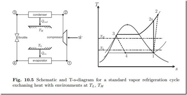
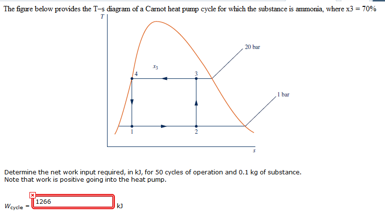
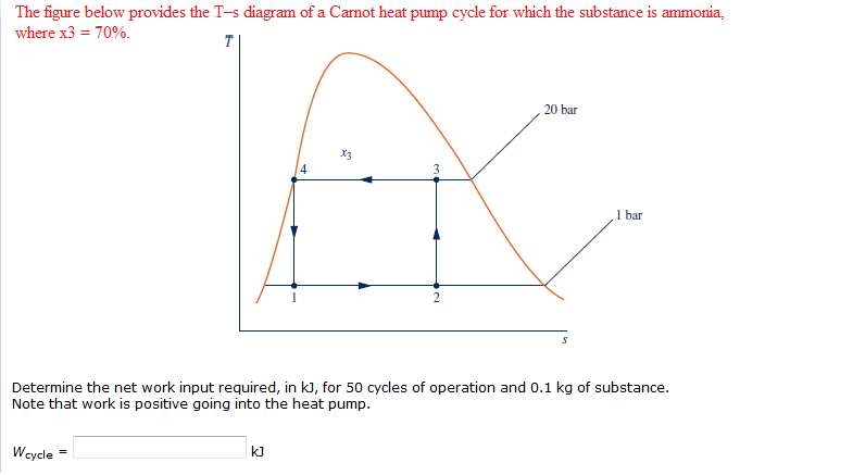
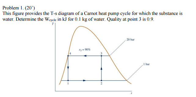
The system used electronic expansion valve EEV to control discharge superheat DSH by using Pd and Td for refrigerant flow adjustment. Provides the heat input to the evaporator of a high-temperature cycle eg 2 units in series Normally a different refrigerant would be used in each separate cycle in order to match the desired ranges of T P. A refrigerator or heat pump that operates on the reversed Carnot cycle is called a Carnot refrigerator or a Carnot heat pump. 1 depicts the pressure-enthalpy p-h and temperature-entropy T-s diagram of a generic heat pump process for an azeotropic refrigerant under sub-critical operation. Or heat pump cycles by controlling the process direction.
 Source: study.com
Reversing the Carnot cycle does reverse the directions of heat and work interactions. Cyclic process of a simple compression refrigeration system Compressor power. So all of the net heat transfer into the system for the cycle shown in our TS Diagram is converted into shaft work. I Describe the temperatures shown in the figure with respect to the operational temperatures they refer to. Stirling engine is a closed cycle regenerative heat engine.
 Source: naomileahdesigns.com
DHW by heat pump and boiler System diagram 13 VR 70 configuration 1 11 System diagram 13 -5 12 Item Description Item Description 1 Heat generator 25 Solar pump unit 2 Heater generator pump 26a Solar charging system 2a Swimming pool circulation pump 26b Drinking water station 2b CHP system circulation pump 27 Cylinder charging pump. So all of the net heat transfer into the system for the cycle shown in our TS Diagram is converted into shaft work. T-s diagram and major components for Carnot refrigerator. The heat pump gets its heat from the surrounding air. Stirling cycle ts diagram.
 Source: researchgate.net
Electrical requirem en ts ca b f ou d h rating plate located. Chapter 11 Refrigeration Cycles The Objective Of A Refrigerator Is. DHW by heat pump and boiler System diagram 13 VR 70 configuration 1 11 System diagram 13 -5 12 Item Description Item Description 1 Heat generator 25 Solar pump unit 2 Heater generator pump 26a Solar charging system 2a Swimming pool circulation pump 26b Drinking water station 2b CHP system circulation pump 27 Cylinder charging pump. Slide 14 of 53. So all of the net heat transfer into the system for the cycle shown in our TS Diagram is converted into shaft work.

LOCATION UOF HEAT P MP. Even-Heat Control Diagram 17 Contact Infomation 18. The heat pump gets its heat from the surrounding air. Reversing the Carnot cycle does reverse the directions of heat and work interactions. The direction of the cyclic process in theT-s diagram determines w hether this is a heat pump cycle refrigeration cycle or a work machine cycle steam power cycle.
 Source: chegg.com
Reversing the Carnot cycle does reverse the directions of heat and work interactions. The reversed Carnot cycle is the most efficient refrigeration. The temperature-entropy diagram Ts diagram in which the thermodynamic state is specified by a point on a graph with specific entropy s as the horizontal axis and absolute temperature T as the vertical axis. A device which used to warm the desired space by using the reversed Carnot cycle is known as a heat pump. Electrical Data ECM Motor Secondary Pump 58 TS Series Wiring Diagram Matrix 59 Typical Wiring Diagram Single Phase TS Units with CXM Controller 60 Typical Wiring Diagram Three Phase TS Units with DXM2 Controller 61.
 Source: slidetodoc.com
Refrigeration cycles are anti-clockwise and the work represented by the green area is added to the cycle. 1 depicts the pressure-enthalpy p-h and temperature-entropy T-s diagram of a generic heat pump process for an azeotropic refrigerant under sub-critical operation. Because the net variation in state properties during a. Therefore recirculation of the cold air off the top of the unit should be avoided. A temperatureentropy diagram or Ts diagram is a thermodynamic diagram used in thermodynamics to visualize changes to temperature and specific entropy during a thermodynamic process or cycle as the graph of a curveIt is a useful and common tool particularly because it helps to visualize the heat transfer during a process.
 Source: machineryequipmentonline.com
1 represents a simple one-stage heat pump the schematic of which may be seen in Fig. 1 depicts the pressure-enthalpy p-h and temperature-entropy T-s diagram of a generic heat pump process for an azeotropic refrigerant under sub-critical operation. Stirling cycle ts diagram. A reversing valve allows this heat pump to operate in both heating and cooling modes. The heat pump gets its heat from the surrounding air.

Cyclic process of a simple compression refrigeration system Compressor power. Electrical requirem en ts ca b f ou d h rating plate located. Chapter 11 Refrigeration Cycles The Objective Of A Refrigerator Is. So the bottom line is that the area enclosed by the process path on the TS Diagram is equal to BOTH Q dot over m-dot AND W Sdot over m-dot as long as the process is an internally reversible steady-state SISO process. So all of the net heat transfer into the system for the cycle shown in our TS Diagram is converted into shaft work.
 Source: study.com
Cyclic process of a simple compression refrigeration system Compressor power. So the bottom line is that the area enclosed by the process path on the TS Diagram is equal to BOTH Q dot over m-dot AND W Sdot over m-dot as long as the process is an internally reversible steady-state SISO process. DHW by heat pump and boiler System diagram 13 VR 70 configuration 1 11 System diagram 13 -5 12 Item Description Item Description 1 Heat generator 25 Solar pump unit 2 Heater generator pump 26a Solar charging system 2a Swimming pool circulation pump 26b Drinking water station 2b CHP system circulation pump 27 Cylinder charging pump. Ii Explain how the reversing valve switches between heating and cooling mode with respect to the. The system used electronic expansion valve EEV to control discharge superheat DSH by using Pd and Td for refrigerant flow adjustment.
 Source: chegg.com
A temperatureentropy diagram or Ts diagram is a thermodynamic diagram used in thermodynamics to visualize changes to temperature and specific entropy during a thermodynamic process or cycle as the graph of a curveIt is a useful and common tool particularly because it helps to visualize the heat transfer during a process. A temperatureentropy diagram or Ts diagram is a thermodynamic diagram used in thermodynamics to visualize changes to temperature and specific entropy during a thermodynamic process or cycle as the graph of a curveIt is a useful and common tool particularly because it helps to visualize the heat transfer during a process. Or heat pump cycles by controlling the process direction. The system used electronic expansion valve EEV to control discharge superheat DSH by using Pd and Td for refrigerant flow adjustment. A device which used to warm the desired space by using the reversed Carnot cycle is known as a heat pump.
 Source: study.com
Thermodynamic heat pump cycles or refrigeration cycles are the conceptual and mathematical models for heat pump air conditioning and refrigeration systems. 1 represents a simple one-stage heat pump the schematic of which may be seen in Fig. 1 depicts the pressure-enthalpy p-h and temperature-entropy T-s diagram of a generic heat pump process for an azeotropic refrigerant under sub-critical operation. I Describe the temperatures shown in the figure with respect to the operational temperatures they refer to. This stirling cycle is classified by 4 idealized thermodynamic processes.
 Source: researchgate.net
Or heat pump cycles by controlling the process direction. Otto Cycle Pv Ts Diagram. SYSTEM CONFIGURATION The schematic diagram of heat pump with discharge superheat DSH control is shown in Figure 1. The system used electronic expansion valve EEV to control discharge superheat DSH by using Pd and Td for refrigerant flow adjustment. HACR circu it and abu of the be nameplate for mini andor An water screen strainer is recommended but it is poor water quality may to unit to the wiring diagram with the ONLY for and wiring be into unit through the holes on the units cabinet.
 Source: researchgate.net
A refrigerator or heat pump that operates on the reversed Carnot cycle is called a Carnot refrigerator or a Carnot heat pump. Reversing the Carnot cycle does reverse the directions of heat and work interactions. HACR circu it and abu of the be nameplate for mini andor An water screen strainer is recommended but it is poor water quality may to unit to the wiring diagram with the ONLY for and wiring be into unit through the holes on the units cabinet. DHW by heat pump and boiler System diagram 13 VR 70 configuration 1 11 System diagram 13 -5 12 Item Description Item Description 1 Heat generator 25 Solar pump unit 2 Heater generator pump 26a Solar charging system 2a Swimming pool circulation pump 26b Drinking water station 2b CHP system circulation pump 27 Cylinder charging pump. Cyclic process of a simple compression refrigeration system Compressor power.
 Source: chegg.com
T S Diagram Of A Generalized Irreversible Carnot Type Heat Pump. Thermodynamic heat pump cycles or refrigeration cycles are the conceptual and mathematical models for heat pump air conditioning and refrigeration systems. Electrical requirem en ts ca b f ou d h rating plate located. The Ts diagram shows an ideal double-cascade system using the same refrigerant in each loop. This stirling cycle is classified by 4 idealized thermodynamic processes.
 Source: researchgate.net
Electrical Data ECM Motor Secondary Pump 58 TS Series Wiring Diagram Matrix 59 Typical Wiring Diagram Single Phase TS Units with CXM Controller 60 Typical Wiring Diagram Three Phase TS Units with DXM2 Controller 61. Stirling engine is a closed cycle regenerative heat engine. It used in winter season at home office hospital schools and colleges. This stirling cycle is classified by 4 idealized thermodynamic processes. The process shown in Fig.
This site is an open community for users to submit their favorite wallpapers on the internet, all images or pictures in this website are for personal wallpaper use only, it is stricly prohibited to use this wallpaper for commercial purposes, if you are the author and find this image is shared without your permission, please kindly raise a DMCA report to Us.
If you find this site beneficial, please support us by sharing this posts to your own social media accounts like Facebook, Instagram and so on or you can also bookmark this blog page with the title heat pump ts diagram by using Ctrl + D for devices a laptop with a Windows operating system or Command + D for laptops with an Apple operating system. If you use a smartphone, you can also use the drawer menu of the browser you are using. Whether it’s a Windows, Mac, iOS or Android operating system, you will still be able to bookmark this website.