High level logical data flow diagram
Home » Background » High level logical data flow diagramYour High level logical data flow diagram images are available. High level logical data flow diagram are a topic that is being searched for and liked by netizens today. You can Find and Download the High level logical data flow diagram files here. Find and Download all royalty-free images.
If you’re searching for high level logical data flow diagram images information related to the high level logical data flow diagram keyword, you have pay a visit to the ideal blog. Our site always gives you suggestions for seeing the maximum quality video and picture content, please kindly search and locate more informative video content and graphics that match your interests.
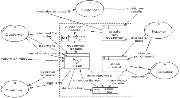
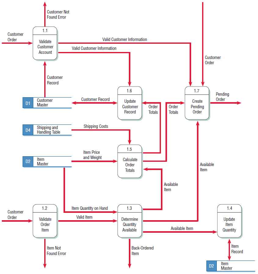
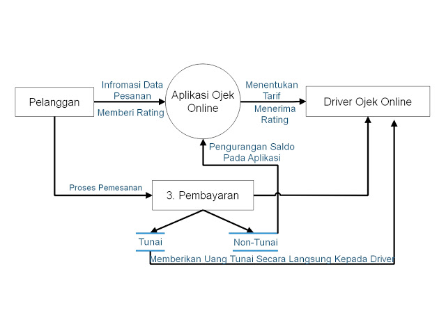
High Level Logical Data Flow Diagram. A data flow diagram can dive into progressively more detail by using levels and layers zeroing in on a particular piece. è Using DFDs for analyzing information systems. Data Flow Diagram DFD A picture of the movement of data between external entities and the processes and data stores within a system Difference from system flowcharts. Create any data flow diagram with minimal effort.
 Pin On Data Flow From pinterest.com
è The differences between current physical current logical new physical and new logical DFDs. June 10 2019 by The Clouds. Higher level DFDs are partitioned into low levels-hacking more information and functional elements. DFD Level 0 is also called a Context Diagram. Higher-level DFDs are partitioned into low levels-hacking more information and functional elements. Easily export it in PNG SVG PDF or JPEG image formats for presentations publishing and printouts.
The technique of decomposition of high level data-flow diagrams to a set of more detailed diagrams provides an overall view of the complete system as well as a more detailed breakdown and description of individual activities where this is.
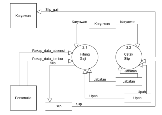
Current Logical Level 0 Diagram 10 Find Customer Record 70 Print Weekly Totals 60 Send Order to Cook 50 Add Customer Record 20 Take Order 30 Print Delivery Order Customer Customer Info Phone Number Customer Order D1 Customer Master Customer Record Customer Record Customer Information D2 Customer History D3 Sales Records Order. A high-level flow chart may include the sub-steps involved and each steps intermediate outputs. The physical data flow diagram below shows certain details not found on the logical data flow diagram above. Data flow diagrams are intended for graphical representation of data flows in the information system and for analysis of data processing during the structural projection. The DFD also provides information about the outputs and inputs of each entity and the process itself. The Architecture Diagrams are the type of diagrams which help to system designers system developers and application developers to visualize the overall high-level structure of the system or application and depict the interactions between software systems users external systems data sources and services.
 Source: id.pinterest.com
The DFD also provides information about the outputs and inputs of each entity and the process itself. The purpose is to express the system scope at a high level as well as to prevent users from deep down into complex details. DFDs depict logical data flow independent of technology Flowcharts depict details of physical systems 7-5 0 2005 by Prentice Hall. The flow is a set of the logic. Data flow diagrams are intended for graphical representation of data flows in the information system and for analysis of data processing during the structural projection.
 Source: researchgate.net
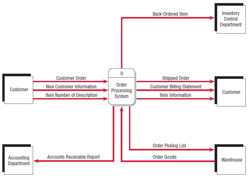
The high-level flow chart provides a birds eye view of the process. It only contains one process node process 0 that generalizes the function of the entire system in relationship to external entities. High Level Workflow Diagram. Levels in DFD are numbered 0 1 2 or beyond. HIGH-LEVEL LOGICAL DATA FLOW DIAGRAM–You can edit this template on Createlys Visual Workspace to get started quickly.
 Source: pinterest.com
It does not go into details as marking all the processes. High-level flow chart. è Balance high-level and low-level DFDs. There are a number of advantages to using a logical model including. The flow is a set of the logic.
 Source: waskhas.com
A context diagram is a top level also known as Level 0 data flow diagram. The necessary level of detail depends on the scope of what you are trying to accomplish. It only contains one process node process 0 that generalizes the function of the entire system in relationship to external entities. Better communication with users. è Balance high-level and low-level DFDs.
 Source: cs.uct.ac.za
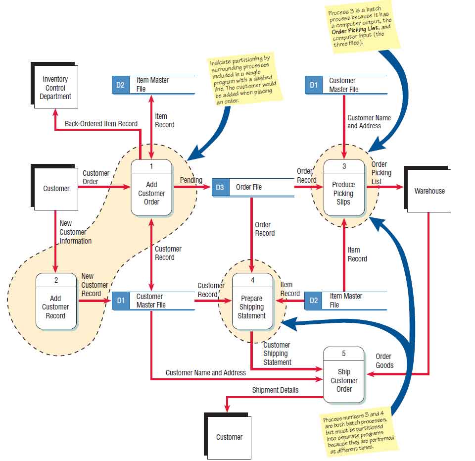
A data flow diagram can dive into progressively more detail by using levels and layers zeroing in on a particular piece. Levels in DFD are numbered 0 1 2 or beyond. Higher level DFDs are partitioned into low levels-hacking more information and functional elements. The necessary level of detail depends on the scope of what you are trying to accomplish. A data flow diagram can dive into progressively more detail by using levels and layers zeroing in on a particular piece.
 Source: pinterest.com
High Level Workflow Diagram. This is very effective for communicating with the business to understand and define the business processes within the enterprise. The physical data flow diagram below shows certain details not found on the logical data flow diagram above. To develop such a diagram first construct a logical data flow diagram for the current system. Data Flow diagrams are used to illustrate the flow of data between applications.
 Source: w3computing.com
A data flow diagram can dive into progressively more detail by using levels and layers zeroing in on a particular piece. To develop such a diagram first construct a logical data flow diagram for the current system. High Level Workflow Diagram. Data Flow Diagram DFD A picture of the movement of data between external entities and the processes and data stores within a system Difference from system flowcharts. DFD levels are numbered 0 1 or 2 and occasionally go to even Level 3 or beyond.
 Source: w3computing.com
A high-level data integration diagram provides the same guidelines as a context diagram does for a data flow diagram. Better communication with users. In Software engineering DFDdata flow diagram can be drawn to represent the system of different levels of abstraction. For example in logical DFDs the processes are business activities. 2 Overview è Process Modeling and Data Flow Diagrams DFDs.
 Source: pinterest.com
The purpose is to express the system scope at a high level as well as to prevent users from deep down into complex details. è The differences between current physical current logical new physical and new logical DFDs. The purpose of the data dissemination diagram is to show the relationship between data entities business services and application componentsThe diagram shows how the logical entities are to be physically realized by application componentsThis allows effective sizing to be carried out and the IT footprint to be refined. There are a number of advantages to using a logical model including. Data flow diagram often used in connection with human process and can be displayed as workflow diagram.
 Source: pinterest.com
The conceptual data model represents the high-level business view. A high-level data integration diagram provides the same guidelines as a context diagram does for a data flow diagram. Intuitive drag and drop interface with precision drawing and control. Higher-level DFDs are partitioned into low levels-hacking more information and functional elements. The flow is a set of the logic.
 Source: pinterest.com
è Draw DFDs of well structured process models. For example in logical DFDs the processes are business activities. A high-level flow chart may include the sub-steps involved and each steps intermediate outputs. 0-level DFD 1-level DFD and 2-level DFD. In Software engineering DFDdata flow diagram can be drawn to represent the system of different levels of abstraction.
 Source: sekawanmedia.co.id
DFD levels are numbered 0 1 or 2 and occasionally go to even Level 3 or beyond. The DFD also provides information about the outputs and inputs of each entity and the process itself. Higher-level DFDs are partitioned into low levels-hacking more information and functional elements. The purpose is to express the system scope at a high level as well as to prevent users from deep down into complex details. External entities processes data stores and data flows.
 Source: technologyuk.net
The purpose is to express the system scope at a high level as well as to prevent users from deep down into complex details. Context data flow diagram also called Level 0 diagram uses only one process to represent the functions of the entire system. 2 Overview è Process Modeling and Data Flow Diagrams DFDs. A basic process picture is what such a flow chart provides. Data flow diagrams are composed of four elements.
 Source: guratgarut.com
It does not go into details as marking all the processes. This is very effective for communicating with the business to understand and define the business processes within the enterprise. Data Flow diagrams are used to illustrate the flow of data between applications. It only contains one process node process 0 that generalizes the function of the entire system in relationship to external entities. In physical DFDs the processes are software programs manual procedures or other ways information is processed.
 Source: waskhas.com
Levels in DFD are numbered 0 1 2 or beyond. Data flow diagram often used in connection with human process and can be displayed as workflow diagram. DFDs depict logical data flow independent of technology Flowcharts depict details of physical systems 7-5 0 2005 by Prentice Hall. But the elements represent different perspectives in logical DFDs than in physical DFDs. Data Flow Diagram DFD A picture of the movement of data between external entities and the processes and data stores within a system Difference from system flowcharts.
 Source: w3computing.com
A context diagram is a top level also known as Level 0 data flow diagram. è Using DFDs for analyzing information systems. 0-level DFD 1-level DFD and 2-level DFD. But the elements represent different perspectives in logical DFDs than in physical DFDs. In Software engineering DFD data flow diagram can be drawn to represent the system of different levels of abstraction.
 Source: pinterest.com
Data Flow diagrams are used to illustrate the flow of data between applications. Levels in DFD are numbered 0 1 2 or beyond. A data-flow diagram has no control flow there are no decision rules and no loops. Architecture and Design RAIDD is used to manage the Risks Assumptions Issues Decisions and Dependencies log. DFD levels are numbered 0 1 or 2 and occasionally go to even Level 3 or beyond.
 Source: guratgarut.com
The high-level logical data integration model in Figure 36 provides the structure for what will be needed for the data integration system as well as provides the outline for the logical models such as extract data quality transform and load components. è Balance high-level and low-level DFDs. 100s of pre-drawn data flow diagram. A high-level data integration diagram provides the same guidelines as a context diagram does for a data flow diagram. Context data flow diagram also called Level 0 diagram uses only one process to represent the functions of the entire system.
This site is an open community for users to submit their favorite wallpapers on the internet, all images or pictures in this website are for personal wallpaper use only, it is stricly prohibited to use this wallpaper for commercial purposes, if you are the author and find this image is shared without your permission, please kindly raise a DMCA report to Us.
If you find this site value, please support us by sharing this posts to your preference social media accounts like Facebook, Instagram and so on or you can also bookmark this blog page with the title high level logical data flow diagram by using Ctrl + D for devices a laptop with a Windows operating system or Command + D for laptops with an Apple operating system. If you use a smartphone, you can also use the drawer menu of the browser you are using. Whether it’s a Windows, Mac, iOS or Android operating system, you will still be able to bookmark this website.