How to draw a timing diagram for a circuit
Home » Wallpapers » How to draw a timing diagram for a circuitYour How to draw a timing diagram for a circuit images are ready. How to draw a timing diagram for a circuit are a topic that is being searched for and liked by netizens now. You can Find and Download the How to draw a timing diagram for a circuit files here. Find and Download all royalty-free photos.
If you’re looking for how to draw a timing diagram for a circuit pictures information related to the how to draw a timing diagram for a circuit interest, you have visit the ideal blog. Our site frequently gives you hints for seeking the highest quality video and picture content, please kindly surf and locate more informative video content and images that fit your interests.
How To Draw A Timing Diagram For A Circuit. The above circuit diagram is for the 1-minute timer circuit. 1 Minute Timer Circuit. As you see timing diagrams together with digital circuits can completely describe the circuits working. In the 3-bit ripple counter three flip-flops are used in the circuit.
 Timing Diagram An Overview Sciencedirect Topics From sciencedirect.com
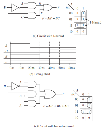
Timing diagram for F A BC Time waveforms for F 1 F 4 are identical except for glitches 6 Hazards and glitches glitch. For the same case if Q and Q were 1 and 0 respectively then X 1 1 and X 2 0 which would result in Q 0 and hence Q 1. Even when engineers have access to digital simulators they still need to draw timing diagrams to help clarify the operation of critical sections of a design. The above circuit diagram is for the 1-minute timer circuit. Assuming the D flip-flops are positive-edge triggered like the 74HC74 and all of the flip-flops are initially reset Q low Q high then a rising edge clock pulse on vstup will set the first flip-flop high. The waveforms show how the state of the signal changes with time.
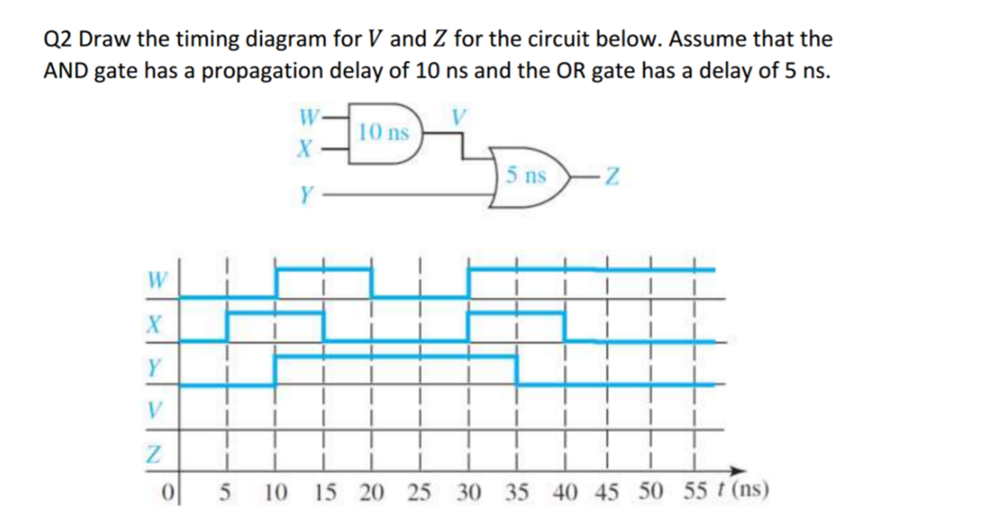
The total time is 10nS 5nS so the horizontal time needs to be at least 8 x 15 120nS.
What is the count sequence. After one minute of time duration the LED will automatically turn ON. Signal B is 1 05 falling 57 0 720 changing 2030 c. For 5 min 10 min and 15 min you just have to change the resistor value R 1. The first circuit diagram shows how a transistors and a few other passive components may be connected for acquiring the intended delay timing outputs. To be able to make timing diagram you need to present these five major components namely the lifeline state timeline duration constraint time.
 Source: youtube.com
To understand the timing diagrams you should follow all symbols and transitions in timing diagrams. We have to configure 555 Timer in Mono-Stable mode to build a timer. To be able to make timing diagram you need to present these five major components namely the lifeline state timeline duration constraint time. Next place the following call to the timing waveform rendering function at the bottom of your web page. For a basic example lets take something we already know and build a diagram around it.
 Source: researchgate.net
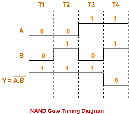
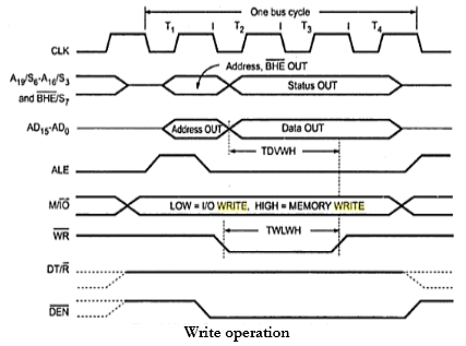
As a timing diagram specifically deals with the sequencing of steps youll invariably find the clock signal at the very top because that is what governs the rise and fall of your signalling empire. For the same case if Q and Q were 1 and 0 respectively then X 1 1 and X 2 0 which would result in Q 0 and hence Q 1. Use Text and Diagrams Together. With a timing diagram the cause-effect relationships between signal transitions are shown by timing parameters like delays setups and holds. But once you understand the whole picture you can easily read any timing.
 Source: youtube.com
Sometimes its difficult to understand the descriptions especially if they contain a lot of different numbers. To be able to make timing diagram you need to present these five major components namely the lifeline state timeline duration constraint time. Construct a 4-bit ripple counter use an input square wave of suitable frequency 1Hz from the signal. The first circuit diagram shows how a transistors and a few other passive components may be connected for acquiring the intended delay timing outputs. As a timing diagram specifically deals with the sequencing of steps youll invariably find the clock signal at the very top because that is what governs the rise and fall of your signalling empire.
 Source: youtube.com
The above circuit diagram is for the 1-minute timer circuit. To draw diagrams like this you just change an input and then follow it through all circuit to see how it changes the state of various elements. Assuming the D flip-flops are positive-edge triggered like the 74HC74 and all of the flip-flops are initially reset Q low Q high then a rising edge clock pulse on vstup will set the first flip-flop high. Glitches occur when different pathways have different delays Causes circuit noise Dangerous if logic makes a decision while output is unstable. To be able to make timing diagram you need to present these five major components namely the lifeline state timeline duration constraint time.
 Source: youtube.com
1 Minute Timer Circuit. The total time is 10nS 5nS so the horizontal time needs to be at least 8 x 15 120nS. The first circuit diagram shows how a transistors and a few other passive components may be connected for acquiring the intended delay timing outputs. With a timing diagram the cause-effect relationships between signal transitions are shown by timing parameters like delays setups and holds. For the same case if Q and Q were 1 and 0 respectively then X 1 1 and X 2 0 which would result in Q 0 and hence Q 1.
 Source: chegg.com
It comes with description language rendering engine and the editor. The 555 Timer starts timing when switched ON. As here n value is three the counter can count up to 2 3 8 values ie. Why use a timing diagram editor. Timing diagram for F A BC Time waveforms for F 1 F 4 are identical except for glitches 6 Hazards and glitches glitch.
 Source: youtube.com
As here n value is three the counter can count up to 2 3 8 values ie. Next if J 1 K 0 Q 1 and Q 0 then X 1 X 2 0 which results in Q 1 and thus Q 0. Therefore you always have to look at these diagrams in combination with the accompanying text. Use Text and Diagrams Together. For the same case if Q and Q were 1 and 0 respectively then X 1 1 and X 2 0 which would result in Q 0 and hence Q 1.
 Source: gacaffe.net
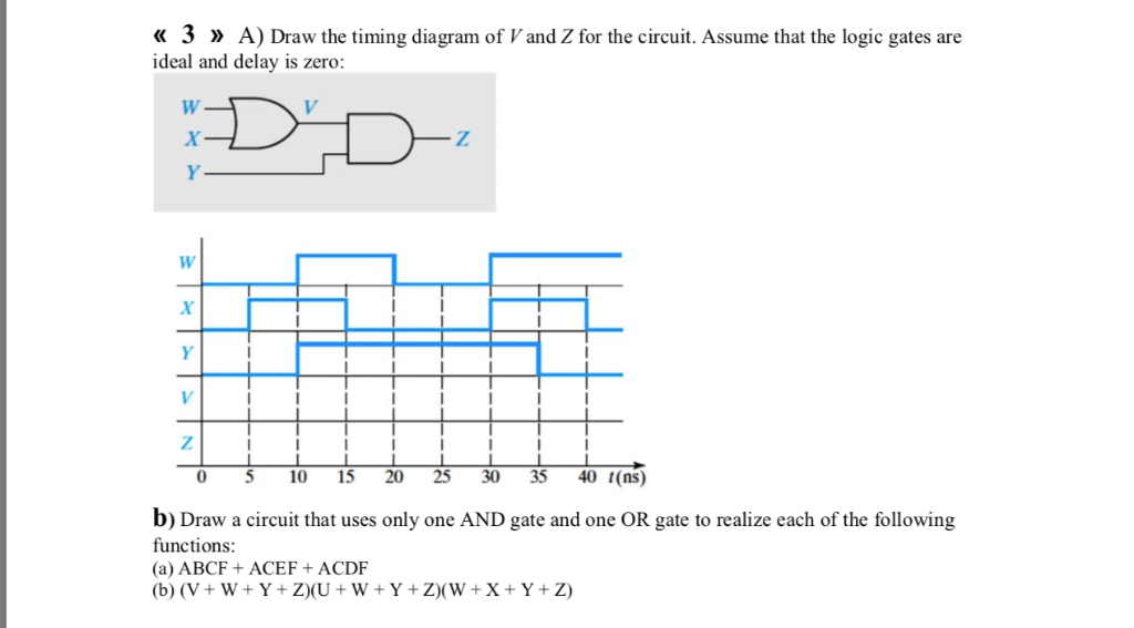
Next place the following call to the timing waveform rendering function at the bottom of your web page. You can find plenty of symbols in timing diagrams. In this case the F output is also low at the start because that is the logic of the circuit. Signal B is 1 05 falling 57 0 720 changing 2030 c. Therefore you always have to look at these diagrams in combination with the accompanying text.
 Source: gatevidyalay.com
But once you understand the whole picture you can easily read any timing. In the 3-bit ripple counter three flip-flops are used in the circuit. The 4 horizontal lines can be labeled A B C and F. The total time is 10nS 5nS so the horizontal time needs to be at least 8 x 15 120nS. To understand the timing diagrams you should follow all symbols and transitions in timing diagrams.
 Source: youtube.com
It comes with description language rendering engine and the editor. Enable the Containers shape library and then drag one horizontal container onto the canvas to represent the first participant in the process. Then you can draw a timing diagram anywhere in your page by inserting JSON code inside a bracket like this. WaveDrom editor works in the browser or can be installed on your system. A LED which is used here just indication purposes behaves like the collector load of the circuit.
 Source: questionpapershub.com
Timing diagram for F A BC Time waveforms for F 1 F 4 are identical except for glitches 6 Hazards and glitches glitch. Glitches occur when different pathways have different delays Causes circuit noise Dangerous if logic makes a decision while output is unstable. The 555 Timer starts timing when switched ON. The above circuit diagram is for the 1-minute timer circuit. To be able to make timing diagram you need to present these five major components namely the lifeline state timeline duration constraint time.
 Source: texample.net
As stated above every company has its own style when it comes to timing diagrams. Timing diagrams show timing relationships between different signals inside an electronic circuit. Unwanted output A circuit with the potential for a glitch has a hazard. To be able to make timing diagram you need to present these five major components namely the lifeline state timeline duration constraint time. To draw diagrams like this you just change an input and then follow it through all circuit to see how it changes the state of various elements.
 Source: holooly.com
Construct a 4-bit ripple counter use an input square wave of suitable frequency 1Hz from the signal. Draw three voltage waveforms one each for A B and C showing all eight possible combinations of A B and C. Then you can draw a timing diagram anywhere in your page by inserting JSON code inside a bracket like this. Timing diagram for F A BC Time waveforms for F 1 F 4 are identical except for glitches 6 Hazards and glitches glitch. The circuit diagram and timing diagram are given below.
 Source: sciencedirect.com
Then you can draw a timing diagram anywhere in your page by inserting JSON code inside a bracket like this. Signal C is changing 010 0 1015 rising 1518 1 1825 changing 2530. But once you understand the whole picture you can easily read any timing. For a basic example lets take something we already know and build a diagram around it. The above circuit diagram is for the 1-minute timer circuit.
 Source: electrical4u.com
A Timing diagram is a type of UML diagram that represents the change in state or value of one or more objects over some time. Time is on the horizontal axis and volts on the vertical axis. The first circuit diagram shows how a transistors and a few other passive components may be connected for acquiring the intended delay timing outputs. To understand the timing diagrams you should follow all symbols and transitions in timing diagrams. But once you understand the whole picture you can easily read any timing.
 Source: chegg.com
Why use a timing diagram editor. A Timing diagram is a type of UML diagram that represents the change in state or value of one or more objects over some time. The 555 Timer starts timing when switched ON. In the 3-bit ripple counter three flip-flops are used in the circuit. What is the count sequence.
 Source: chegg.com
Sometimes its difficult to understand the descriptions especially if they contain a lot of different numbers. For a basic example lets take something we already know and build a diagram around it. Time is on the horizontal axis and volts on the vertical axis. This implies that if J 0 and K 1 then the flip-flop resets Q 0 and Q 1. Next place the following call to the timing waveform rendering function at the bottom of your web page.
 Source: gacaffe.net
After one minute of time duration the LED will automatically turn ON. With a timing diagram the cause-effect relationships between signal transitions are shown by timing parameters like delays setups and holds. Well build out a timing diagram that describes how to use the buttons of our 74HC595. Construct a 4-bit ripple counter use an input square wave of suitable frequency 1Hz from the signal. The total time is 10nS 5nS so the horizontal time needs to be at least 8 x 15 120nS.
This site is an open community for users to do submittion their favorite wallpapers on the internet, all images or pictures in this website are for personal wallpaper use only, it is stricly prohibited to use this wallpaper for commercial purposes, if you are the author and find this image is shared without your permission, please kindly raise a DMCA report to Us.
If you find this site convienient, please support us by sharing this posts to your favorite social media accounts like Facebook, Instagram and so on or you can also save this blog page with the title how to draw a timing diagram for a circuit by using Ctrl + D for devices a laptop with a Windows operating system or Command + D for laptops with an Apple operating system. If you use a smartphone, you can also use the drawer menu of the browser you are using. Whether it’s a Windows, Mac, iOS or Android operating system, you will still be able to bookmark this website.